Tuesday, May 1, 2018

Civil 3D Polyline Tools

When I was a kid I recall my dad using the phrase 'a day late and a dollar short' off and on. I know that last week I said I'd be posting these weekly now and given that I'm a day late on this post, hopefully it's still helpful to you.

I tend to do a lot of work with grading and Civil 3D Surface. My workflow in grading has been to utilize all types of Civil 3D grading tools (feature lines, grading groups, corridors, etc) and ultimately paste surfaces together to create a final surface. Often in this work I find myself having to create boundaries for my various surfaces to 'clip' the surface so that it is ready for pasting. With this, you end up working a lot with polylines, thus this post is sort of a collection of polyline tools both native to the software and then some additional 3rd party tools / code that can assist in generating and cleaning up polyline boundaries.

Extracting Polyline Boundaries from Surfaces

For generating boundaries on corridor surfaces, I feel these two commands get overlooked - but are very fast and helpful.

Create Polyline from Corridor
  • Command Syntax: _AeccCreateSubFromPline
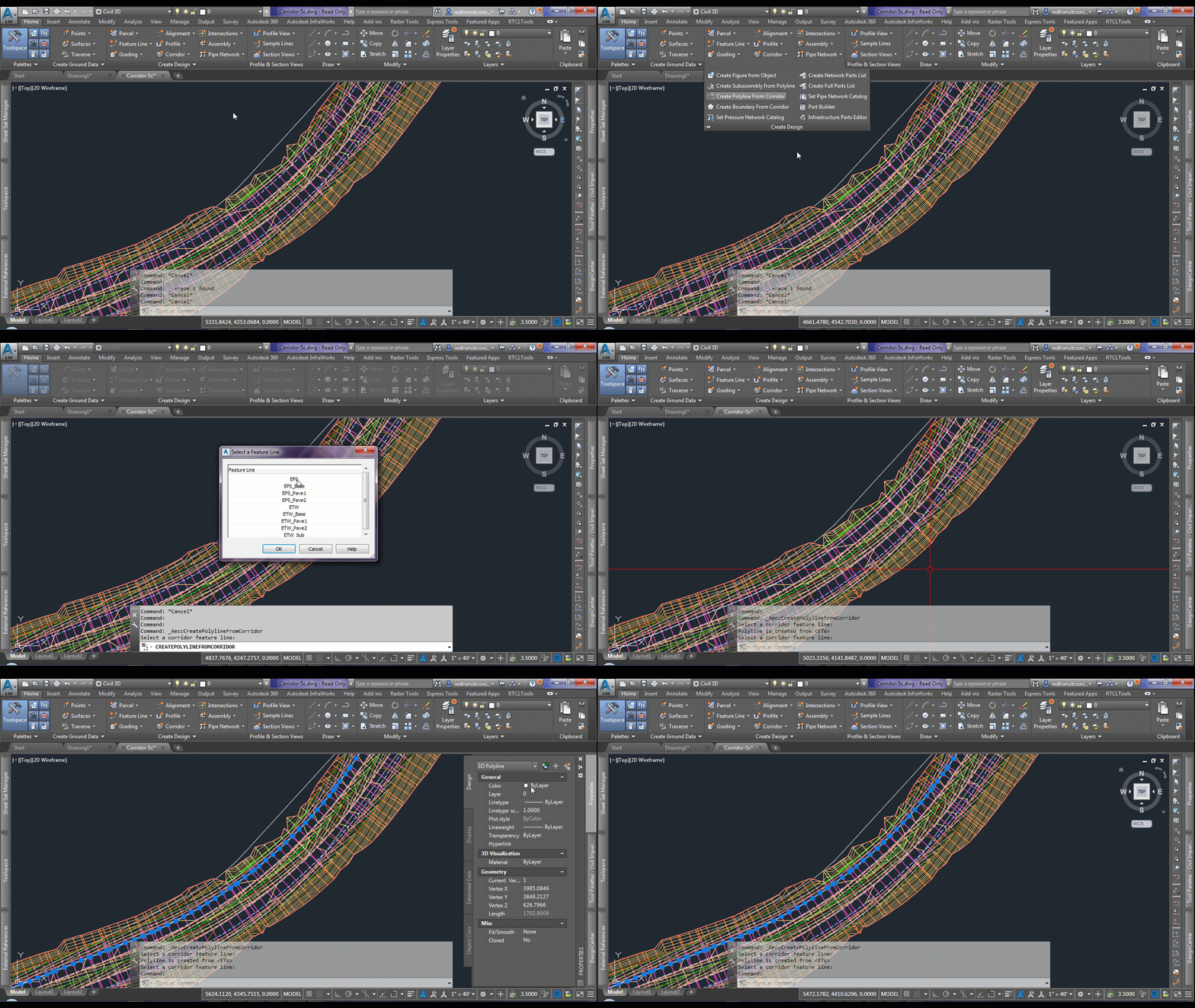
 

Create Boundary from Corridor
  • Command Syntax: _AeccCreateBoundaryFromCorridor

General Surface Object Extraction
  • Command Syntax: _AeccSurfaceExtractObjects
I don't have much to say out about the native Surface Object Extraction tool other than it's cumbersome and a bit of pain to use. Make sure whatever you want to extract is turned on in your surface style prior to running the tool (my biggest pet peeve of this native tool). To help with this, I have a free command line tool that allows you to quickly modify a style's object visibility here on the Autodesk App Store.

95% of the time I'm using this for extracting boundaries, thus I'm in the works of a new utility to extract boundaries to be available on the Autodesk App Store soon... more to come on this!


Conversion of 3D Polylines and 2D Polylines

I believe these next three commands are fairly wide known and used within the Civil 3D community, but for sake of those new to the software, I'll list them out; these are routinely used in my workflows.

Convert 2D to 3D Polylines
  • Command Syntax: _AeccConvertPlines
Convert 3D to 2D Polylines
  • Command Syntax: _AeccConvert3dPolys


Flatten Objects

  • Command Syntax: Flatten

This command will help remove elevations from lines, arcs, polylines, 3D Polylines and more in a quick selection of objects.

Determining Issues with Polylines

Perhaps one of the most frustrating and time intensive parts is trying when you are trying to join a polyline and it will not join, or once you have a polyline joined and closed, attempting to add it to a surface and finding the polyline will not add. These issue can typically be resolved by running the three previously mentioned commands, but also checking your polyline for intersections.

Self Intersecting Polylines
How do you check if your polyline has intersections? And if it does, how do I know where the intersections occur? There are no native commands to assist with this that I am aware of.

CAD Studio has a great free LISP utility that can help you find where the intersections of a self intersecting polyline occur here and there's more documentation on it here.

Alternatively, if you have someone that can handle .NET programming, there's some great starter code to do this here. For myself, I've used this code and then added a circle at the intersection points in which I can then find the circles on screen and quickly correct the issue.


Find Polyline End Location
When you are working with a polyline that thousands of vertices and loops back in on itself, it can be beneficial to know where the start/end location is. This will help you to quickly get to that location and make potential edits to resolve the issue. One can do this through the Properties palette as shown below


or, you can do this with a this great little lisp routine shared by the Greg Battin on the AutoCAD Tips Blog that helps to locate gaps in polylines.

Weed Features
  • Command Syntax: _AeccWeedFeatures
  • If you have too many vertices in your extracted boundary from a surface you may want to weed out some of the vertices - beware not to go too far in the weeding however as you could end up clipping off the exact location a surface ties into the existing grade - use your best judgement on this. Here's more on this command
Explode, Flatten, and Rejoin
When in doubt of the issue, don't waste your time trying to figure it out. First change the polyline layer and isolate it, explode at least twice to get it down to basic linework, flatten, and rejoin the polyline.

Linework Commands

These commands tend to be missed I think, but are extremely powerful. I'll list the top three favorites here but there are quite a few. I suggest looking into what all these commands do and how you can leverage them in your workflows.

Linework Shrinkwrap
  • Command Syntax: LINEWORKSHRINKWRAP

Linework Divide
  • Command Syntax: LINEWORKDIVIDE

Linework Trim
  • Command Syntax: LINEWORKTRIM

Many more... just type in LINEWORK and you can see them all listed.

Boundary Area
  • Command Syntax: BPOLY or BOUNDARY
  • This command is more well known, but ultimately allows you to pick inside an area similar to the hatch command and get the boundary as a polyline... just make sure you isolate layers first.

Summary

Overall, when I'm working with on a specific boundary that has a lot of vertices and data to work with, I use a multitude of these commands - but here's my general workflow using Autodesk's Praxis Workflow Editor


Monday, April 23, 2018

Creating Points Along an Alignment by Specified Stations


I recently had a project in which I need to import a set of points along an alignment to locate some bridge pier locations. The locations were provided to me via a Microsoft Word document as Stations along the alignment like shown below

One could manually type in these locations along the alignment with the command to Create Points Station / Offset option, but that would take time to do and would introduce more chances for human error in typing in the stations and offsets.

Alternatively, I chose to convert the table provided into Microsoft Excel and import the data using the the Create Points Import From File option as shown below.


In order to do this, there was a few minutes of manipulating the data into Microsoft Excel by doing the following:

  1. Highlight and Copy the table in Microsoft Word
  2. Paste into a blank Excel spreadsheet
  3. Reorder the columns provided to be in the following format: Station, Offset, Description (Pier Number). Note: Additional format options are available and can bee seen from command line screen shots below.
  4. Set the Offset column to be 0 in order to have the points fall directly on the alignment
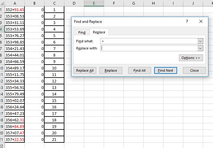
  5. Replace the station format into numerical format - to do this, do a find and replace for "+" and replace with nothing.
  6. Save the Microsoft Excel spreadsheet as a CSV file, comma delimited.
  
Data in Microsoft Excel

Data in Notepad viewing the CSV file

Next, in a Civil 3D file containing the Alignment, run the Create Points Import From File option shown on one of the above screenshots. Select the CSV file and follow the command line prompts. You'll need to specify the File format by entering in the corresponding number 1 - 6, the delimiter format corresponding number 1 or 2, and an Invalid indicator for Station Offset - default -99999. The invalid indicator is used for points that can't be computed due to offset issue or for being outside the extents of the alignment.


Overall, this process took me about 5 minutes to bring the data in. To save even more time if the stations were to change frequently, I would provide the source of the data with a Microsoft Excel spreadsheet setup numerically, formatted to show the stations, in the order needed to easily import the data as this would save additional time.

For more information, see this Autodesk Knowledge Network page

Friday, December 30, 2016

Stage Storage Alternatives

Let's face it... the Stage Storage Tool in Civil 3D needs a complete overhaul. The only time it works for me without having to do a bunch of extra work, is on a cleanly graded design surface. Seems that most of my work is incorporating existing data which is never good enough for the Stage Storage Tool. So I ran across some links in explaining alternative methods that I need to try... saving these so I don't forget and you're welcome to look into as well. Hopefully, they provide great results that can create less work in making the software do what I want so I can focus on the design...

ALTERNATIVE STAGE STORAGE TECHNIQUE – CIVIL 3D TABLES

STAGE STORAGE ANALYSIS OF STOCKPILES/DAM WALLS (BETWEEN TWO IRREGULAR SURFACES)

Tuesday, November 3, 2015

Wednesday, July 22, 2015

Civil 3D Users Looking for Work?

Looking for an experienced CAD Operator/Designer in Chicago with Civil 3D experience in Chicago.

See Job Posting on LinkedIn

Monday, October 27, 2014

Missing Or Hidden Dialog Boxes in AutoCAD

Ever have dialogs disappear in AutoCAD and not be able to access them without what seems to be CTRL-ALT-DEL and exiting the software? This blog post helped me out greatly to solving the issue when using multiple monitors and the dialogs disappearing: http://autodesk.typepad.com/beyondthebox/2013/10/missing-or-hidden-dialog-boxes-in-autocad.html

Additionally, I've had some app dialogs disappear and the command remains running but inaccessible due to accidentally clicking off of the dialog. How do you gain access back? Here's an example and how.

Here I've used an app from the app store and the dialogs appear - (App is Set Multiple Object Styles for Civil 3D)

 In the image below, I've accidentally clicked off of the dialog and the focus goes back to AutoCAD Civil 3D. The dialog has disappeared but the command is still running - see command line. No obvious way to access the dialog.
However, we can get around this issue by cycling through our running applications using ALT + TAB. Then use the arrow keys to move over the AutoCAD Civil 3D icon, at which point you will see text noting the dialog that is currently running. Upon selecting the AutoCAD Civil 3D icon the running dialogs will appear again allowing for selection and completion of the command.


Tuesday, February 25, 2014

Civil 3D Slope Across Pipes App

Have you been looking for a better workflow in assigning slopes to pipes, especially when they are not needed to be analyzed in Storm Sewers or Storm and Sanitary Analysis? There's a new app for that on the app store now!!

Check out Slope Across Pipes here.

This app allows for quickly setting the slope of a number of pipes within a common pipe network and applying pipe drop across each structure. The app allows for selecting pipes/structures in plan view or pipes/structures in profile view and offers two modes - by slope and by inverts. When selecting parts in profile view, the app also provides the ability to extract the selected point elevation from the profile to apply to the pipe network. For both modes, the app does not care if the upstream or downstream end is selected, nor does it care if the start and end points of the pipes are in the same configuration throughout. When applying pipe drops in structures, the app checks to see if the structure is not a null structure before applying.

App running via Plan View


 App running via Profile Slope Mode Upstream to Downstream

 App running via Slope Mode Downstream to Upstream
 
 App running via Profile Inverts Mode Downstream to Upstream

 App running via Profile Inverts Mode Upstream to Downstream