Here is a great post from Augusto Goncalves regarding the Autodesk Exchange app plugins. Some may have seen duplicate 'Plug-In' or 'Add-In' ribbon tabs when installing apps from the store. A simple change to your CUI will solve this issue.
http://adndevblog.typepad.com/infrastructure/2012/12/duplicated-add-ins-tab-on-civil-3d.html?utm_source=feedburner&utm_medium=feed&utm_campaign=Feed%3A+InfrastructureModelingDevblog+%28Infrastructure+Modeling+DevBlog+%29
Monday, December 10, 2012
New FREE Autodesk Exchange App
Red Transit Consultants has a new Civil 3D Surface Style Toggle app out on the Autodesk Exchange Store and the best part is... the app is FREE!!
See the post and follow the blog here:
http://www.redtransitconsultants.com/blog/c3d-surface-style-toggle-free-app
Then go download the app!! Available for Civil 3D 2013.
See the post and follow the blog here:
http://www.redtransitconsultants.com/blog/c3d-surface-style-toggle-free-app
Then go download the app!! Available for Civil 3D 2013.
Saturday, November 24, 2012
Red Transit Consultants, LLC now has two apps available on the Autodesk Exchange store. The Civil3D Copy, Raise/Lower Profile app helps to speed up your daily workflows when having to copy, raise/lower existing dynamic profiles. The app saves you about 15 clicks through several dialog boxes. The Civil3D Set Multiple Object Styles app is also an efficiency workflow app when dealing with objects styles for alignments, profiles, and surfaces. When having to set object styles, the app can save you countless clicks and dialogs reducing all operations to one dialog window.
The 2013 version apps are available for purchase here (Copy, Raise/Lower Profile) and here (Set Multiple Object Styles). We also have 2011 and 2012 versions of both apps available, just send a request.
Red Transit Consultants, LLC has one other app, the Civil3D Find and Replace, seen on this blog that is currently in the review process with the Autodesk Exchange team. That app should be available in the next couple of weeks.
Subscribe to the Red Transit Consultants, LLC blog here!!
Tuesday, November 20, 2012
Autodesk Exchange Store
If you haven't heard about the new Autodesk Exchange store, take some time and go check it out. There are a lot of apps for AutoCAD, Civil 3D, Map, etc. If you're looking for tools to help you through projects, you can find them here. Civil 3D and Map were just recently added (I believe earlier this year).
With the development of the Autodesk Exchange store, I have decided to start my own app development business and offer some of the commands I have created and posted on here. Feel free to go and check out Red Transit Consultants, LLC. The apps I post will have YouTube videos and links to the store where you can download.


With the development of the Autodesk Exchange store, I have decided to start my own app development business and offer some of the commands I have created and posted on here. Feel free to go and check out Red Transit Consultants, LLC. The apps I post will have YouTube videos and links to the store where you can download.
Friday, August 10, 2012
Civil3D Large Object Support
Today I have the joy of designing a 4.5 mile roadway. I thought, no big deal, until I received a message I hadn't seen before.

The blog, Being Civil, has a good explanation of what happening with this message, should you ever be as lucky to me to receive it.

The blog, Being Civil, has a good explanation of what happening with this message, should you ever be as lucky to me to receive it.
Wednesday, July 11, 2012
Convert C3D Surface to DEM File
Ran into this issue today and found out some interesting things... DEM files are only in metric, and thought C3D looks like it will convert on the fly, it will not. Found this blog for a solution.
Sunday, June 10, 2012
Civil 3D Find and Replace
Have you have had to rename a lot of different objects in Civil 3D? Or even have to change the descriptions?
For instance if you grade in a channel, you might make an alignment called Channel 5, which will also have a profile called Channel 5, which is on a profile view called Channel 5, which has an assembly called Channel 5, which all makes up a corridor called Channel 5, which has a corridor surface called Channel 5, which is pasted in a surface with a name reference to Channel 5. Then the engineer decides to renumber the channels... now your channel is Channel 100. Oh and there are about 15 different channels like this in your drawing. Good luck making sure everything reads as it should for the next person who uses the file.
This drove me to write a new command... C3D Find and Replace. I mean we can do a find and replace on regular text, why not on names and descriptions of objects???
Here are a few screenshots and a video showing the command in action.


You can watch the command in action here.
Thursday, June 7, 2012
Copy Surface Profile and Perform Raise/Lower Command
For those of you who read my posts, you probably have realized that I am all about less clicks and less menus. Civil3D can get somewhat confusing with the hidden operations to perform specific tasks. One of those very tasks that is somewhat hidden is the copy profile from surface procedure. There are a number of dialogs that you must go through and change a setting from static to dynamic, then get into the profile geometry editor, make a copy of the profile, go back and change the original profile's setting back to dynamic. You can find more detailed explanation of how to do this here and here.
In order to save more clicks and to speed up the process, I automated it programmatically. In this first image, the code begins with prompting for a selection of a profile. The 'prmpt.AddAllowedClass' line tells the software what type of object we are looking for. Anything other than a profile will return the reject message listed above. Next, this command was built for copying surface profiles, thus we perform an if/then statement on the selected profile type to verify the type is EG type. Note that the EG type stands for existing ground, though the user could create a profile on a proposed surface, and that would perform the same way.
Next we prompt for a raise or lower value. Upon copying, the command will adjust the PVI values automatically. This command also places a corresponding name and description on the profile, thus you'll see the if then statement checking the value of the typed in distance. If it's negative, it will display LOWERED, if it's positive it will display RAISED.
See the first image below.

The second image we arrive at the TRY statement, we have to gather information about the selected profile. So we store data about the profile in 'alignment', 'layerId', 'surfaceId', styleId' and 'labelSetId'. Note that these are all the items a profile requires to create from a surface. After gathering the previous profile information, I set the new profile name and the new profile description. I have set mine up to read as the following:
SelectedProfileName [COPY - RAISED/LOWERED XX'
The description will read something similar. Next we create the new profile as an ObjectId with all of the gathered information of the selected profile. Then we need to open that newly created profile and make sure the program knows to select it. Then I set the update mode to static and the description from the string above.
Now to adjust the PVIs. Here we perform a ForEach loop to check through all the PVIs in the new profile. We gather the current PVI elevation, add that to the selected value of offset (+/-), then change the PVI elevation. Finally we close the initial If/then statement with some kind of error message should the user pick a FG (finished grade profile), and commit the transaction.
See the second image below.

I'm fairly new to VB.net and the Civil3D API, so I don't know if this was the best method for this operation, but it definitely works!!
Wednesday, June 6, 2012
Eric Chappell's Blog: Upright Linetypes - Gotcha!
Here is a great post by Eric Chappell about 2012's upright linetype feature. Too bad I'm using 2011. So ready to switch!!
Eric Chappell's Blog: Upright Linetypes - Gotcha!: Recently we upgraded to Civil 3D 2012 and one of the things I was really excited about was actually an AutoCAD 2011 feature that enabled tex...
Eric Chappell's Blog: Upright Linetypes - Gotcha!: Recently we upgraded to Civil 3D 2012 and one of the things I was really excited about was actually an AutoCAD 2011 feature that enabled tex...
Sunday, June 3, 2012
Apply Surface Style to Multiple Surfaces in One Click
Civil 3D is a great tool. However, there are some commands and workflows that I come across during use that I think to myself "there has got to be a better way!!" One of those thoughts came to me a couple weeks ago in working with surfaces. The majority of my work is grading plans, thus I deal with a lot of surfaces. My grading plans typically consist of portions of my site (access road, pad, pits, channels, etc) all on separate surfaces, then pasted together into one compiled surface. This workflow works well when having to make modifications as you only have to work with a small area instead of a large surface.
The issue I found becomes in displaying these surfaces. The compiled surface is the one that is shown and all labels are based off of, the other surfaces are working surfaces and are only displayed when modifications are being made. Thus when coming into the drawing file I first have to turn the compiled surface to 'NO DISPLAY' then go through each of the working surfaces and turn them to a style that is displayed. Not a huge deal, but takes time and many clicks, so here's my thought - "there has to be a better way!!"
Well there is. Handle the surface displays programmatically with a new command. I'm simply calling this command 'Set Multiple Surface Styles' or from the command line, just type 'SMSS'.
Basically the command auto populates a pull down box with all the surface styles available in your current drawing and it populates a checkable list of surfaces in your current drawing. (Note: all surfaces are populated as there are four types in Civil 3D: Tin Surface, Grid Surface, Tin Volume Surface, and Grid Volume Surface.) Select the style desired and check which surfaces to apply it to, then click apply. For those that like to pick on screen, I have offered that option as well. For me personally, I've offered an expanded version of the command allowing for two different styles to be applied to surfaces all at once. (It's less clicks yet... I'm all about less clicks!!) I've also included a toolbar with a few buttons for formatting the lists; buttons include Sort, Check all, Uncheck all, and Invert Selection.
Here are some screen shots of the dialogs:

MAIN DIALOG

MAIN DIALOG

EXPANDED DIALOG
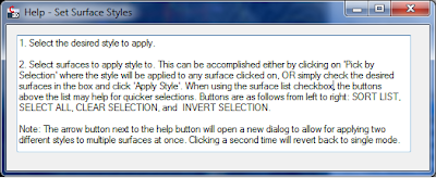
HELP MENU
As being fairly new to VB.net programming, this command was a bit difficult for me. I am currently using Civil 3D 2011, which is what the command was written in, however, it should work in older and newer versions - though it has not been tested. I initially thought I could write this command in VB.net, however the surfaces have not been fully exposed in 2011 from COM. So with a little help from JEFF_M on www.theswamp.org, he provided me with a method to call the vb.net surface and transfer it to a COM format for applying the style. Feel free to take a look at the posting here, if you'd like. This command opens up the door for other possibilities. I'm working on expanding the command for other style/object types and will post an updated version in the near future to look something like this:

FUTURE VERSION FOR ADDITIONAL STYLE/OBJECT TYPES
If you like this command and would like a copy of it you can find the DLL file here. Just type in NETLOAD in the command line and select the file. Then use "SMSS" to run the command.
If you like the command, but would like the source code for the command you can download the VB.net project here.
Feel free to let me know what you think of it!!
Thursday, May 24, 2012
Civil 3D Audit Commands
Have you ever run into major errors in your grading files and can't figure out what is wrong? Ever run the Audit command and it says surface error, then you look at the definition of the surface and it create a snapshot and no longer references actual feature lines, grading groups, etc.? What about disappearing feature lines and grading groups?
These are issues my colleagues and myself have ran into over the years. I have been looking for a fix for a while now, and I think I may have found a solution.
Here is a post by the CAD Geek referring to some of these issues, which then forwards you on to the Being Civil Blog post about Undocumented Commands, which then points to the (now documented) Autodesk page referring to these commands.
From what I understand, you would first run the 'AeccFindSiteOverlaps' command on each site. The command will tell you if there are erros and which of the following commands should be run to remove overlapping geometry: 'AeccRemoveDupFeatureLines', 'AeccRemoveAlignmentsFromSite', or 'AeccRemoveDupLotLines'.
Wednesday, May 16, 2012
Publishing Autodesk Civil3D Data into a 3D Web Viewer
I recently ran into a situation where I needed to allow multiple people access to a DWF file. You can easily email the file around to people, then they would need to install the free DWF viewer available on Autodesk website. From there they can open the file and view.
But what if that is just too many steps for the situation? Autodesk has a product called Autodesk Freewheel and can be found here. This allows you to post content to DWF files that are stored out on the web. Below are a couple of examples of these. The first is a 2D drawing package from the Autodesk Freewheel site. The second is an example of a 3D DWF I created from Civil3D with both Civil3D objects and basic AutoCAD objects, then published to a 3D DWF file.
In adding the file to the web, I first attempted using Google Docs which turned out to be unsuccessful. Google Docs which creates a hyperlink that no longer contains the DWF file name and only allows for the file to be downloaded for viewing. My next attempt was through Dropbox, which does work. I placed the file in my public folder and copied the link to the file. Dropbox also creates a separate hyperlink, but keeps the file extension allowing for Autodesk Freewheel to access the file.
Please note on the Autodesk Freewheel page that within the hyperlinks additional code is needed to set the view to start point. For 3D DWFs this can be quite nerve racking trying to set the view where you want it. Here is a good workflow I used to set the starting view.
1. Use Mozilla Firefox for your internet browser.
2. Load the viewer onto your webpage, then go view the webpage through Mozilla Firefox.
3. Set the view using the viewer to how you want it to start.
4. Right click on the view and go to "This Frame, View Frame Info" as shown in the image below.
5. When the window pops up, go to Media and browse through the view links until you find the last full path, as shown in the image below. This will be the settings for your current view.
6. Right click, and copy the path.
7. Update the path on your web page to the copied path. Note be sure that the beginning path first calls up the Autodesk Freewheel web program (ie. Everything before "path=", your model path should follow the "path=").
8. Go and verify that the page loads correctly.

STEP 4

STEP 5
Autodesk Freewheel also allows for a free rendering service that provides a link to your DWF model. Here is a sample of my 3D DWF rendered through the model.
Tuesday, May 15, 2012
Color Specific Cut/FIll Surface Labels
Today I had a project where I needed to designate fill labels and cut labels with different colors and signs (+/-) to add to a volume surface. From what I recall from AU classes and have read online, there isn't a real easy way to do this, so I began doing a little research and found the following link. This page is good and works pretty well, except if you have to put a (+) sign in front of the positive numbers. In doing this you will find that the red cut numbers show up underneath the positive numbers - I thought there has to be a better way.
This began my venture into trying to utilize expressions to perform this same calculation. I created two expressions that check to see if the surface elevation is a positive number, or a negative number. Basically if the findings return a true value, then give me the Surface Elevation, and if it's false give me 0. (Note that expressions are only used for math equations and do not functions with strings). Here is an example of one of these expressions:

Next, since the above expression returns either the surface elevation or 0, I setup my spot elevation label to have a cut component and a fill component. Each component has different colors and references different expressions in the contents field. The image below is an example of the cut component referencing a the above expression within the contents - the difference between this and the link above is that the sign can remain set to a positive or negative based on what the number is. Upon setting both components up, you will see both components over top of one another - this needs to be adjust to make one "not show up" - and I quote this because you have to sort of trick the software into doing this.

Both components also reference a text size expression. The text size expression idea came from an Autodesk University class called "Exploit Expressions to Enhance Your Labels" by Brian Hailey and can be found here. His idea was to basically make the text you don't want to see really small so it does not plot, since there is no way to completely turn these off. I suppose you could take it a step further and change it's position to locate the text somewhere off in lala land as well. Anyways, I setup a separate expression to perform this task and can be seen in the image below. The results of the label style are shown at the bottom - enjoy!!


Thursday, April 26, 2012
Draw Order Extended
In my last post, I mentioned that I have been working on modifying the Draw Order By Layer command found on the Autodesk Labs Plugin of the month page here. I think I have pretty much perfected it to the best of by ability and for what I wanted it to do.
First, I added additional tabs for other items needed to adjust draw order. The tabs added were XREFs, Blocks, Civil3D Surfaces, and a Checked Items Tab. Now, many of these items could have been moved to a separate layer and then adjusted via the basic Draw Order By Layer tab, but for many of these items, that goes against company standards. We typically put all of our XREFs on one XREF layer and Civil3D surfaces automatically go on one surface layer, so why not just allow for adjustment of these items? The blocks tab was added for me personally as many times I might have the same block on multiple layers and need to adjust accordingly for all instances, thus selecting the block name made sense. The checked items tab I think is the coolest, as it allows for you to work with all object on a selected layer (or multiple layers), XREF objects selected, and blocks selected - and if you think outside the box it will handle all Civil3D surfaces via the layer the surfaces go on. Trust me, I tried to incorporate Civil3D surfaces to this list as well, but Civil3D would crash hard when adjusting - and I'm not sure why.
Here is what the command looks like:
The best workflow I have found with the command is to begin by adjusting your surfaces in the order they should display. You'll see from the image examples below the existing surface was brought over the analysis surface. Once completed rerun the command and select the necessary layers (include the default surface layer), and/or XREFs, and/or Blocks, then go to the Selected Items tab and use the update button on the far left to generate the list of checked items. Re-order everything in the desired order from top to bottom (surfaces most likely at bottom) and you'll see in the last image everything has been updated.
--------------------------------------------------------------------------------------------------------------------------------------------------
AutoCAD Civil3D 2011 Version - as shown above
--------------------------------------------------------------------------------------------------------------------------------------------------
Zip File
If you are interested in the Zip file for the actual code, you can download from here.
DLL File
If you are interested in the dll file for the plugin command, you can download from here. Then run the NETLOAD command in Civil3D and select the file. The command will runs with the command DOEXT.
--------------------------------------------------------------------------------------------------------------------------------------------------
--------------------------------------------------------------------------------------------------------------------------------------------------
AutoCAD 2011 Version - minus the Surfaces tab shown above
--------------------------------------------------------------------------------------------------------------------------------------------------
Zip File
If you are interested in the Zip file for the actual code, you can download from here.
DLL File
If you are interested in the dll file for the plugin command, you can download from here. Then run the NETLOAD command in Civil3D and select the file. The command will runs with the command DOEXT.
--------------------------------------------------------------------------------------------------------------------------------------------------
First, I added additional tabs for other items needed to adjust draw order. The tabs added were XREFs, Blocks, Civil3D Surfaces, and a Checked Items Tab. Now, many of these items could have been moved to a separate layer and then adjusted via the basic Draw Order By Layer tab, but for many of these items, that goes against company standards. We typically put all of our XREFs on one XREF layer and Civil3D surfaces automatically go on one surface layer, so why not just allow for adjustment of these items? The blocks tab was added for me personally as many times I might have the same block on multiple layers and need to adjust accordingly for all instances, thus selecting the block name made sense. The checked items tab I think is the coolest, as it allows for you to work with all object on a selected layer (or multiple layers), XREF objects selected, and blocks selected - and if you think outside the box it will handle all Civil3D surfaces via the layer the surfaces go on. Trust me, I tried to incorporate Civil3D surfaces to this list as well, but Civil3D would crash hard when adjusting - and I'm not sure why.
Here is what the command looks like:


The best workflow I have found with the command is to begin by adjusting your surfaces in the order they should display. You'll see from the image examples below the existing surface was brought over the analysis surface. Once completed rerun the command and select the necessary layers (include the default surface layer), and/or XREFs, and/or Blocks, then go to the Selected Items tab and use the update button on the far left to generate the list of checked items. Re-order everything in the desired order from top to bottom (surfaces most likely at bottom) and you'll see in the last image everything has been updated.


--------------------------------------------------------------------------------------------------------------------------------------------------
AutoCAD Civil3D 2011 Version - as shown above
--------------------------------------------------------------------------------------------------------------------------------------------------
Zip File
If you are interested in the Zip file for the actual code, you can download from here.
DLL File
If you are interested in the dll file for the plugin command, you can download from here. Then run the NETLOAD command in Civil3D and select the file. The command will runs with the command DOEXT.
--------------------------------------------------------------------------------------------------------------------------------------------------
--------------------------------------------------------------------------------------------------------------------------------------------------
AutoCAD 2011 Version - minus the Surfaces tab shown above
--------------------------------------------------------------------------------------------------------------------------------------------------
Zip File
If you are interested in the Zip file for the actual code, you can download from here.
DLL File
If you are interested in the dll file for the plugin command, you can download from here. Then run the NETLOAD command in Civil3D and select the file. The command will runs with the command DOEXT.
--------------------------------------------------------------------------------------------------------------------------------------------------
Wednesday, April 25, 2012
AutoCAD VB.net Programming with DXFCODEs
Over the last couple of weeks I've been working with the code for the January 2011 release of DrawOrder by Layer for AutoCAD on the Autodesk Labs Plugin of the month page which can be found here. The code uses a selection filter via the DXFCODE protocol to find the layer names matching the strings in the list generated from the block table record. I am currently revising this command to add some additional items and will post it once it is complete. Here is what the code looks like to select objects on the selected layer:
For Each lay As String In revLst
Dim psr As PromptSelectionResult
Dim tvs(0) As TypedValue
tvs(0) = New TypedValue(DxfCode.LayerName, lay)
Dim sf As New SelectionFilter(tvs)
psr = ed.SelectAll(sf)
If psr.Value IsNot Nothing Then
dot.MoveToTop(New ObjectIdCollection(psr.Value.GetObjectIds))
End If
pm.MeterProgress()
System.Windows.Forms.Application.DoEvents()
Next
While doing this I have been looking through the DXFCODE format codes in VB.net and have been trying to find a list of what these all do and what they are for. I found a pretty good list here, also displayed below in relation to the {}Autodesk.AutoCAD.DatabaseServices namespace. Note that these are in order by the group code and not alphabetical.
| Group Name | Group Code | Description |
|---|---|---|
| Invalid | -9999 | |
| XDictionary | -6 | |
| PReactors | -5 | APP: persistent reactor chain |
| Operator | -4 | APP: conditional operator (used only with ssget) |
| FirstEntityId, XDataStart | -3 | APP: extended data (XDATA) sentinel (fixed) |
| Header | -2 | APP: entity name reference (fixed) |
| End | -1 | APP: entity name. The name changes each time a drawing is opened. It is never saved (fixed) |
| Start | 0 | Text string indicating the entity type (fixed) |
| Text, XRefPath | 1 | Primary text value for an entity |
| AttributeTag, BlockName, MlineStyleName, ShapeName, SymbolTableName, SymbolTableRecordName | 2 | Name (attribute tag, block name, and so on) |
| AttributePrompt, CLShapeName, Description, DimensionAlternativePrefixSuffix, DimPostString, DimStyleName, LinetypeProse, SymbolTableRecordComments, TextBigFontFile, TextFontFile | 3-4 | Other text or name values |
| DimensionBlock, Handle | 5 | Entity handle; text string of up to 16 hexadecimal digits (fixed) |
| DimBlk1, LinetypeName | 6 | Linetype name (fixed) |
| DimBlk2, TextStyleName | 7 | Text style name (fixed) |
| LayerName | 8 | Layer name (fixed) |
| CLShapeText | 9 | DXF: variable name identifier (used only in HEADER section of the DXF file) |
| XCoordinate | 10 | Primary point; this is the start point of a line or text entity, center of a circle, and so on DXF: X value of the primary point (followed by Y and Z value codes 20 and 30 APP: 3D point (list of three reals) |
| YCoordinate | 20 | DXF: Y values of the primary point |
| ZCoordinate | 30 | DXF: Z values of the primary point |
| Elevation | 38 | DXF: entity's elevation if nonzero |
| Thickness | 39 | Entity's thickness if nonzero (fixed) |
| PixelScale, Real, ShapeScale, ShapeXOffset, ShapeYOffset, TxtSize, TxtStylePSize, TxtStyleXScale, ViewBackClip, ViewFrontClip, ViewHeight, ViewLensLength, ViewportAspect, ViewportHeight,ViewWidth, | 40-48 | Floating-point values (text height, scale factors, and so on) |
| LinetypeScale | 48 | Linetype scale; floating-point scalar value; default value is defined for all entity types |
| DashLength, LinetypeElement, MlineOffset | 49 | Repeated floating-point value. Multiple 49 groups may appear in one entity for variable-length tables (such as the dash lengths in the LTYPE table). A 7x group always appears before the first 49 group to specify the table length |
| Angle, ViewportSnapAngle, ViewportTwist | 50-58 | Angles (output in degrees to DXF files and radians through AutoLISP and ObjectARX applications) |
| Visibility | 60 | Entity visibility; integer value; absence or 0 indicates visibility; 1 indicates invisibility |
| LayerLinetype | 61 | Layer Linetype |
| Color | 62 | Color number (fixed) |
| HasSubentities | 66 | "Entities follow" flag (fixed) |
| ViewportVisibility | 67 | Space-that is, model or paper space (fixed) |
| ViewportActive | 68 | APP: identifies whether viewport is on but fully off screen; is not active or is off |
| ViewportNumber | 69 | APP: viewport identification number |
| CircleSides, Int16, LinetypeAlign, LinetypePdc, RegAppFlags, TxtStyleFlags, ViewMode, ViewportGrid, ViewportIcon, ViewportSnap, ViewportSnapPair, ViewportSnapStyle, ViewportZoom | 70-78 | Integer values, such as repeat counts, flag bits, or modes |
| Int32 | 90-99 | 32-bit integer values |
| Subclass | 100 | Subclass data marker (with derived class name as a string). Required for all objects and entity classes that are derived from another concrete class. The subclass data marker segregates data defined by different classes in the inheritance chain for the same object. This is in addition to the requirement for DXF names for each distinct concrete class derived from ObjectARX (see "Subclass Markers") |
| EmbeddedObjectStart | 101 | |
| ControlString | 102 | Control string, followed by "{ |
| DimVarHandle | 105 | Object handle for DIMVAR symbol table entry |
| UcsOrg | 110 | |
| UcsOrientationX | 111 | |
| UcsOrientationY | 112 | |
| XReal | 140 | |
| ViewBrightness | 141 | |
| ViewContrast | 142 | |
| Int64 | 160 | 64-bit integer values |
| XInt16 | 170 | 16-bit integer values |
| NormalX | 210 | Extrusion direction (fixed)DXF: X value of extrusion direction APP: 3D extrusion direction vector |
| NormalY | 220 | DXF: Y values of the extrusion direction |
| NormalY | 230 | DXF: Z values of the extrusion direction |
| XXInt16 | 270 | |
| Int8 | 280 | 8-bit integer values |
| RenderMode | 281 | |
| Bool | 290-299 | Boolean flag value |
| XTextString | 300-309 | Arbitrary text strings |
| BinaryChunk | 310-319 | Arbitrary binary chunks with same representation and limits as 1004 group codes: hexadecimal strings of up to 254 characters represent data chunks of up to 127 bytes |
| ArbitraryHandle | 320-329 | Arbitrary object handles; handle values that are taken "as is." They are not translated during INSERT and XREF operations |
| SoftPointerId | 330-339 | Soft-pointer handle; arbitrary soft pointers to other objects within same DXF file or drawing. Translated during INSERT and XREF operations |
| HardPointerId | 340-349 | Hard-pointer handle; arbitrary hard pointers to other objects within same DXF file or drawing. Translated during INSERT and XREF operations |
| SoftOwnershipId | 350-359 | Soft-owner handle; arbitrary soft ownership links to other objects within same DXF file or drawing. Translated during INSERT and XREF operations |
| HardOwnershipId | 360-369 | Hard-owner handle; arbitrary hard ownership links to other objects within same DXF file or drawing. Translated during INSERT and XREF operations |
| LineWeight | 370-379 | Lineweight enum value (AcDb::LineWeight). Stored and moved around as a short. Custom non-entity objects may use the full range, but entity classes only use 371-379 DXF group codes in their representation, because AutoCAD and AutoLISP both always assume a 370 group code is the entity's lineweight. This allows 370 to behave like other "common" entity fields. |
| PlotStyleNameType | 380-389 | PlotStyleName type enum (AcDb::PlotStyleNameType). Stored and moved around as a short. Custom non-entity objects may use the full range, but entity classes only use 381-389 DXF group codes in their representation, for the same reason as the Lineweight range above. |
| PlotStyleNameId | 390-399 | String representing handle value of the PlotStyleName object, basically a hard pointer, but has a different range to make backward compatibility easier to deal with. Stored and moved around as an Object ID (a handle in DXF files) and a special type in AutoLISP. Custom non-entity objects may use the full range, but entity classes only use 391-399 DXF group codes in their representation, for the same reason as the Lineweight range above. |
| ExtendedInt16 | 400-409 | 16-bit Integers |
| LayoutName | 410-419 | String |
| ColorRGB | 420 | |
| ColorName | 430 | |
| Alpha | 440 | |
| GradientObjectType | 450 | |
| GradientPatType | 451 | |
| GradientTintType | 452 | |
| GradientColCount | 453 | |
| GradientAngle | 460 | |
| GradientShift | 461 | |
| GradientTintVal | 462 | |
| GradientColVal | 463 | |
| GradientName | 470 | |
| Comment | 999 | DXF: The 999 group code indicates that the line following it is a comment string. SAVEAS does not include such groups in a DXF output file, but OPEN honors them and ignores the comments. You can use the 999 group to include comments in a DXF file that you've edited |
| ExtendedDataAsciiString | 1000 | ASCII string (up to 255 bytes long) in extended data |
| ExtendedDataRegAppName | 1001 | Registered application name (ASCII string up to 31 bytes long) for extended data |
| ExtendedDataControlString | 1002 | Extended data control string ("{"or "}") |
| ExtendedDataLayerName | 1003 | Extended data layer name |
| ExtendedDataBinaryChunk | 1004 | Chunk of bytes (up to 127 bytes long) in extended data |
| ExtendedDataHandle | 1005 | Entity handle in extended data; text string of up to 16 hexadecimal digits |
| ExtendedDataXCoordinate | 1010 | A point in extended data DXF: X value (followed by 1020 and 1030 groups) APP: 3D point |
| ExtendedDataWorldXCoordinate | 1011 | A 3D world space position in extended data DXF: X value (followed by 1021 and 1031 groups) APP: 3D point |
| ExtendedDataWorldXDisp | 1012 | A 3D world space displacement in extended data DXF: X value (followed by 1022 and 1032 groups) APP: 3D vector |
| ExtendedDataWorldXDir | 1013 | A 3D world space direction in extended data. DXF: X value (followed by 1022 and 1032 groups) APP: 3D vector |
| ExtendedDataYCoordinate | 1020 | DXF: Y and Z values of a point |
| ExtendedDataWorldYCoordinate | 1021 | DXF: Y and Z values of a world space position |
| ExtendedDataWorldYDisp | 1022 | DXF: Y and Z values of a world space displacement |
| ExtendedDataWorldYDir | 1023 | DXF: Y and Z values of a world space direction |
| ExtendedDataZCoordinate | 1030 | DXF: Y and Z values of a point |
| ExtendedDataWorldZCoordinate | 1031 | DXF: Y and Z values of a world space position |
| ExtendedDataWorldZDisp | 1032 | DXF: Y and Z values of a world space displacement |
| ExtendedDataWorldZDir | 1033 | DXF: Y and Z values of a world space direction |
| ExtendedDataReal | 1040 | Extended data floating-point value |
| ExtendedDataDist | 1041 | Extended data distance value |
| ExtendedDataScale | 1042 | Extended data scale factor |
| ExtendedDataInteger16 | 1070 | Extended data 16-bit signed integer |
| ExtendedDataInteger32 | 1071 | Extended data 32-bit signed long |
Tuesday, April 3, 2012
VB.net Programming for AutoCAD, Civil 3D, and Map 3D
Over my 15 years of using AutoCAD and other Autodesk software, I've fooled around with writing LISP routines to a very beginner type extent. I've taken classes at Autodesk University on LISP and some of the APIs of the various softwares, but it's been over my head for a lot of it. Within the last month or so, I finally decided to start learning VB.net programming. After a few weeks into it and some coaching help from a friend, I finally wrote my first command - needless to say I am hooked.
The command I wrote automates a process in Map 3D that I despised doing. The process involves labeling GIS data of soil boundaries. I typically bring these in from a SHP file, Create Object Data, and import as polylines. From here the labeling process begins with the Map Annotation commands. To initiate the annotation, the user must first define a template for the annotation, in this case a Soils Label. Within the template, Edit Annotation Text msut be inserted (typically with the "MAPANNTEXT" command). This text is a special kind of attibute text that allows for accessing the Object Data Tables and Fields. Thus the user would browse to the correct table and field to generate labels based on the selected boundary's Object Data. From here the template would be saved.
Upon completion of the template, the user would then use the Map Annotation Insert template command, call up the created template and could insert once at a picked point, or insert for entire drawing at the centroid of the object. Typically the fastest way to do this is via the centroid of the object, however, the centroid does not always occur within the soil boundary - thus you would then have to move the labels around and check properties of each boundary to ensure the label is inside the correct boundary.

My VB.net command automates this entire process, which in turn saves a lot of trivial time of moving labels around. Basically to explain the command in english, it first calls up the dialog shown below and provides some instruction. It then auto populates the Table Name based on the Object Data in the drawing, then allows for the user to type in the corresponding Field Name for the soil name. From here the user can click "Label Boundaries" in which the program checks to see if an annotation template with the name of SoilLbl has been created. If not it creates the template based on the given prompts on the dialog.
Next it prompts the user to select a boundary to label, then prompts for label insertion point and repeats the label insertion point prompt until the user hits escape. Essentially this allows the user to lable one boundary at a time, ensuring for more accurate labeling of soil boundaries, and less time involved of going through the above process.

I would like to encourage everyone to jump into the coding!! It opens a whole new realm of AutoCAD, Civil 3D, and Map 3D.
Civil 3D Labels Showing "XREF Moved"
Last week I ran into an issue where a drawing's Civil 3D labels were displaying XREF Moved as shown in the image below:
 I did some research and found a blog regarding this issue (a link to the blog can be found at the bottom of this page). Though the blog's reasoning for this error may be correct, I found that it was not the solution to the issue I was having. After further research in the drawing, I found that indeed, the XREF had actually been moved. The labels were creating by lableing contours through the XREF, thus when the XREF was moved the labels reflected the error - kudos to Autodesk for thinking of this. Had the labels not stated the XREF was moved, it may not have been noticed by anyone reviewing plans as it was moved a very minor amount.

Track back to original blog solution that was not the solution of my problem.
http://beingcivil.typepad.com/my_weblog/2009/04/xref-moved.html

Track back to original blog solution that was not the solution of my problem.
http://beingcivil.typepad.com/my_weblog/2009/04/xref-moved.html
Chicago Civil 3D User Group
Last we Tuesday we held the first group meeting for the Chicago Civil 3D User Group. It was a success thanks to everyone who came out with interest and support. We had 12 attendees. The next group meeting will be on Tuesday, April 17th from 7:00pm-8:30pm. Definitely looking forward to that meeting as we will be covering the new features of AutoCAD Civil 3D 2013.
Should you or anyone you know be interested in the group, you can view the group page on LinkedIn here: Chicago Civil 3D User Group Page.
Should you or anyone you know be interested in the group, you can view the group page on LinkedIn here: Chicago Civil 3D User Group Page.
Thursday, March 8, 2012
Chicago Civil 3D User Group - Collaboration Meeting
Please join us for the first meeting of the Chicago Civil 3D User Group. We are calling it a Collaboration Meeting, to kickoff the group and get everyone’s input on how to make the group successful. Please see the attached PDF for details. Feel free to share the event as well.
Please be sure to RSVP to me by Friday, March 23rd, so we can plan accordingly for space and refreshments.

Wednesday, February 29, 2012
Chicago Civil 3D User Group
Since moving to Chicago, I've been looking to get involved and interact with other Civil 3D and CAD users and have been unable to find a professional group to join. So, I am starting one!! If you know of anyone in the Chicago region that uses the software interested in joining, please direct them to the LinkedIn group called "Chicago Civil 3D User Group". Looking to have the first group meeting sometime in March.


Autodesk Subassembly Composer for AutoCAD Civil 3D
For those of you Civil 3D users that are big fans of corridors, like me, Autodesk has unveiled the new Subassembly Composer (SAC) recently. I had taken a couple overview classes at Autodesk University this last year, and have been using ever since. For me, SAC brings a whole fresh new aspect to Civil 3D. SAC allows users to create their own fully functioning custom subassemblies that can range from very simplistic to extremely complicated with various programming built in. These custom subassemlies can be huge time savers on projects.
Subassembly Composer Overview
The SAC program has a fairly simplistic interface with various panels that can be moved around the screen for customization. I'd recommend leaving everything where it is, as it makes sense, everything seen is used. See image below.
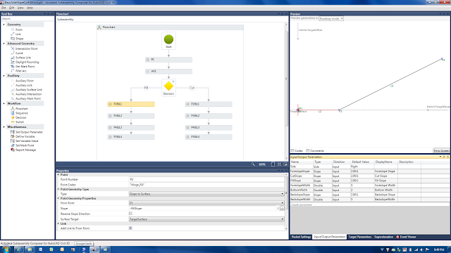
The left hand side contains items in your tool box. If you're familiar with looking through the help menus of various "out of the box" subassemblies, then many of these items will make sense to you.
The center of the window contains the subassembly flowchart. This area helps you visualize how the tools chosen from the tool box relate to one another. From a user standpoint, keeping things clean and organized will make creating a subassmebly much easier. The window directly below the flowchart contains the properties of the tools used. Simply click on an item, and the properties of that item show below.
The lower right window contains several tabs. The first tab, "Packet Settings" allows you to add a subassembly name (referenced in Civil 3D tool space), description of the subassmebly (again referenced in Civil 3D tool space), a help file (PDF, DOCX, or other), and graphic image (for viewing in Civil 3D tool space). Note that the help menu currently does not work for custom subassemblies within Civil 3D; this is a known bug that has not been fixed as of yet.
The next tab is for Input/Output paramters, these show up under subassembly properties, parameters tab within Civil 3D and allow the end user to enter custom values for the components designed in subassembly composer.
 The third tab is for Target Parameters such as surfaces, offset targets, and elevation targets. The fourth tab contains super elevation data should that be needed, and the last tab is for the event viewer. I have only dealt with the first three tabs thus far.
The upper right window, called the preview, is probably one of the most helpful areas of the program. This area displays what the subassembly you are creating should look like, with a few limitations. Items I've noticed are when you apply a surface target, an offset targe, or an offset elevation target to the subassembly,the display changes per the preview settings, on the Target Parameters tab mentioned above. Thus causing the display of the design subassembly to appear differently than you'd expect. I'd recommend adding offset and elevation targets into the subassembly design last to avoid this.
The help menu of SAC is pretty good. It seems to be a forum where users can add information, yet with some sort of control as to what information is added. There are several packet files out there for download to visually see how to use each tool. This was probably the best way that I learned how to use the program. Open up one of the PKT files and view the data, click through the various tools and notice the properties programmed for each. Another good method in learning the software is to try and create one of the simple "out of the box" subassemblies within subassembly composer.
Creating a Subassembly
Firstly, in creating your own subassembly, you have to have a great inspiring idea. However, be sure to not pick something too difficult to handle, or you can quickly become disatissfied that your custom subassembly does not work. My first subassembly turned out to be too difficult to achieve at first, so I had to find another that I could actually complete.
I have been using the Civil 3D subassembly BasicSideSlopeCutDitch subassembly for quite a while and have found it extremely useful in roadway design. In more than one circumstance, engineers have requested that I carry the channel along the toe of the fill slope to pick up additional drainage (as shown in the image below). This can be a difficult process without the use of SAC, basically adding a corridor, then grading in an additional channel with grading groups or corridors, and pasting surfaces together. Thus I had the idea to recreate the BasicSideSlopeCutDitch, but modify it to include a channel in the fill section.

The flowchart for this subassembly is shown in the SAC overview image above and basically begins with a point that would be the hinge point of the subassembly and setting a target surface in the target parameters (set the surface preview to something greater than 0, while point 1 should be a 0,0. Next add in an auxiallry point, auxillary tools are temporary calculation tools and do not show up in Civil 3D visibly. The auxiallry point, needs to be set on the target surface, thus the properties type should be set to "Delta X on Surface", form point can either be point 1 or origin, Delta X would be 0, surface target is the target surface.
Next add in a decision; this is a conditional tool allowing you to provide input for a true/false situations. We need to tell the subassembly to determine if it is in a cut or fill situation. Under the properties of the decision the conditional value needs to check both the auxillary point 1 and point 1 Y values in relation to the target surface. Thus if you type "AP1.Y<P1.Y" you are telling the subassembly that if the distance to surface of the auxillary point is less than the distance to surface of the point, then perform the true option, if not perform the false option. The false option can be renamed to Cut and the true option can be renamed to fill, for organization. The left side of the decision tool is always the true value and the right side is always the cut value.
Next add in a point for both the cut side and the fill side. Connect lines to each from each side of the decision tool, you should see the Fill and Cut text show up in the line. Before moving forward, we need to add in user inputs. Add the following user inputs with the columns in order following, name, type, direction, default value, display name:
Next we need to added properties to each of the points starting with the first point on the cut side. This will be the first slope in the ditch, thus we know what the foreslope slope should be and we know what the foreslope width should be from the parameters created above. Make the point type to be "Slope and Delta X", set the slope to "-ForeslopeSlope", and the Delta X to "ForeslopeWidth". Next we need to establish the bottom of the ditch. This we know the bottom width and the bottom is flat, thus we can use the type "Angle and Delta X" where the angle will be "0" and the Delta X will be "BottomWidth". The next segment is the backslope of the channel and should be programmed similar to the foreslope and the last segment will tie from the top of the backslope to the surface. This segment will have a type of "Slope to Surface" using the CutSlope parameter as the slope and the target surface parameter as the surface target. The preview window should be taking shape now.
The fill slope side will be very similar to the cut slope side, however, the first segment should target the target surface at the fill slope first, then proceed into the foreslope of the channel, add in the bottom width, then target the target surface a second time to close the channel. This will not need a backslope as if a backslope is added, there is the possibility of passing the target surface and thus creating a berm, blocking drainage.
Final cleanup of the subassmebly should involve going through each of the points and lines and adding in point codes and codes for the objects. These should be entered in a similar fashion, ie "Top" and "Datum" should be added to all to create a top surface and datum surface on the subassembly.
Recommended Organizational Methods
For ease on end users, I recommend that prior to finalizing your subassemblies, study the help menu of similar "out of the box" subassemblies and use the same format Autodesk does for Input/Output Parameters, Targer Parameters, Point Codes, and Codes. Keeping various tools in line with one another in the flowchart will make it much easier to follow while programming. Click on a tool and drag, or use the arrow keys for a more refined movement.
Help menues should be made up to look similar to the "out of the box" help menus, at a minimum to provide the same type of information, schematics, and order.
Icons should be of the same format as ones provided. Starting with an "out of the box" icon is a great way to develop a nice looking icon. Program icons can be found here: C:\ProgramData\Autodesk\C3D 2011\enu\Tool Catalogs\Road Catalog\Images
Using the Subassembly in Civil 3D
Using the subassembly in Civil 3D is pretty easy. Simply right click on your tool palette, add a new custom palette, and import subassemblies. Browse to the PKT file saved by subassembly composer, select, and hit ok. Subassembly is now ready for use on the palette the same way all others are used.
Other users who do not have Subassembly Composer installed will need to download and install a patch from Autodesk.
Subassembly Composer Overview
The SAC program has a fairly simplistic interface with various panels that can be moved around the screen for customization. I'd recommend leaving everything where it is, as it makes sense, everything seen is used. See image below.

The left hand side contains items in your tool box. If you're familiar with looking through the help menus of various "out of the box" subassemblies, then many of these items will make sense to you.
The center of the window contains the subassembly flowchart. This area helps you visualize how the tools chosen from the tool box relate to one another. From a user standpoint, keeping things clean and organized will make creating a subassmebly much easier. The window directly below the flowchart contains the properties of the tools used. Simply click on an item, and the properties of that item show below.
The lower right window contains several tabs. The first tab, "Packet Settings" allows you to add a subassembly name (referenced in Civil 3D tool space), description of the subassmebly (again referenced in Civil 3D tool space), a help file (PDF, DOCX, or other), and graphic image (for viewing in Civil 3D tool space). Note that the help menu currently does not work for custom subassemblies within Civil 3D; this is a known bug that has not been fixed as of yet.
The next tab is for Input/Output paramters, these show up under subassembly properties, parameters tab within Civil 3D and allow the end user to enter custom values for the components designed in subassembly composer.

The upper right window, called the preview, is probably one of the most helpful areas of the program. This area displays what the subassembly you are creating should look like, with a few limitations. Items I've noticed are when you apply a surface target, an offset targe, or an offset elevation target to the subassembly,the display changes per the preview settings, on the Target Parameters tab mentioned above. Thus causing the display of the design subassembly to appear differently than you'd expect. I'd recommend adding offset and elevation targets into the subassembly design last to avoid this.
The help menu of SAC is pretty good. It seems to be a forum where users can add information, yet with some sort of control as to what information is added. There are several packet files out there for download to visually see how to use each tool. This was probably the best way that I learned how to use the program. Open up one of the PKT files and view the data, click through the various tools and notice the properties programmed for each. Another good method in learning the software is to try and create one of the simple "out of the box" subassemblies within subassembly composer.
Creating a Subassembly
Firstly, in creating your own subassembly, you have to have a great inspiring idea. However, be sure to not pick something too difficult to handle, or you can quickly become disatissfied that your custom subassembly does not work. My first subassembly turned out to be too difficult to achieve at first, so I had to find another that I could actually complete.
I have been using the Civil 3D subassembly BasicSideSlopeCutDitch subassembly for quite a while and have found it extremely useful in roadway design. In more than one circumstance, engineers have requested that I carry the channel along the toe of the fill slope to pick up additional drainage (as shown in the image below). This can be a difficult process without the use of SAC, basically adding a corridor, then grading in an additional channel with grading groups or corridors, and pasting surfaces together. Thus I had the idea to recreate the BasicSideSlopeCutDitch, but modify it to include a channel in the fill section.

The flowchart for this subassembly is shown in the SAC overview image above and basically begins with a point that would be the hinge point of the subassembly and setting a target surface in the target parameters (set the surface preview to something greater than 0, while point 1 should be a 0,0. Next add in an auxiallry point, auxillary tools are temporary calculation tools and do not show up in Civil 3D visibly. The auxiallry point, needs to be set on the target surface, thus the properties type should be set to "Delta X on Surface", form point can either be point 1 or origin, Delta X would be 0, surface target is the target surface.
Next add in a decision; this is a conditional tool allowing you to provide input for a true/false situations. We need to tell the subassembly to determine if it is in a cut or fill situation. Under the properties of the decision the conditional value needs to check both the auxillary point 1 and point 1 Y values in relation to the target surface. Thus if you type "AP1.Y<P1.Y" you are telling the subassembly that if the distance to surface of the auxillary point is less than the distance to surface of the point, then perform the true option, if not perform the false option. The false option can be renamed to Cut and the true option can be renamed to fill, for organization. The left side of the decision tool is always the true value and the right side is always the cut value.
Next add in a point for both the cut side and the fill side. Connect lines to each from each side of the decision tool, you should see the Fill and Cut text show up in the line. Before moving forward, we need to add in user inputs. Add the following user inputs with the columns in order following, name, type, direction, default value, display name:
- Side, Side, Input, Right, Side
- ForeslopeSlope, Slope, Input, 2.00:1, Foreslope Slope
- CutSlope, Slope, Input, 2.00:1, Cut Slope
- FillSlope, Slope, Input, 2.00:1, Fill Slope
- ForeslopeWidth, Double, Input, 5, Foreslope Width
- BottomWidth, Double, Input, 2, Bottom Width
- Backslope Slope, Slope, 2.00:1, Backslope Slope
- BackslopeWidth, Double, Input, 5, Backslope Width
Next we need to added properties to each of the points starting with the first point on the cut side. This will be the first slope in the ditch, thus we know what the foreslope slope should be and we know what the foreslope width should be from the parameters created above. Make the point type to be "Slope and Delta X", set the slope to "-ForeslopeSlope", and the Delta X to "ForeslopeWidth". Next we need to establish the bottom of the ditch. This we know the bottom width and the bottom is flat, thus we can use the type "Angle and Delta X" where the angle will be "0" and the Delta X will be "BottomWidth". The next segment is the backslope of the channel and should be programmed similar to the foreslope and the last segment will tie from the top of the backslope to the surface. This segment will have a type of "Slope to Surface" using the CutSlope parameter as the slope and the target surface parameter as the surface target. The preview window should be taking shape now.
The fill slope side will be very similar to the cut slope side, however, the first segment should target the target surface at the fill slope first, then proceed into the foreslope of the channel, add in the bottom width, then target the target surface a second time to close the channel. This will not need a backslope as if a backslope is added, there is the possibility of passing the target surface and thus creating a berm, blocking drainage.
Final cleanup of the subassmebly should involve going through each of the points and lines and adding in point codes and codes for the objects. These should be entered in a similar fashion, ie "Top" and "Datum" should be added to all to create a top surface and datum surface on the subassembly.
Recommended Organizational Methods
For ease on end users, I recommend that prior to finalizing your subassemblies, study the help menu of similar "out of the box" subassemblies and use the same format Autodesk does for Input/Output Parameters, Targer Parameters, Point Codes, and Codes. Keeping various tools in line with one another in the flowchart will make it much easier to follow while programming. Click on a tool and drag, or use the arrow keys for a more refined movement.
Help menues should be made up to look similar to the "out of the box" help menus, at a minimum to provide the same type of information, schematics, and order.
Icons should be of the same format as ones provided. Starting with an "out of the box" icon is a great way to develop a nice looking icon. Program icons can be found here: C:\ProgramData\Autodesk\C3D 2011\enu\Tool Catalogs\Road Catalog\Images
Using the Subassembly in Civil 3D
Using the subassembly in Civil 3D is pretty easy. Simply right click on your tool palette, add a new custom palette, and import subassemblies. Browse to the PKT file saved by subassembly composer, select, and hit ok. Subassembly is now ready for use on the palette the same way all others are used.
Other users who do not have Subassembly Composer installed will need to download and install a patch from Autodesk.
Subscribe to:
Posts (Atom)