For those of you Civil 3D users that are big fans of corridors, like me, Autodesk has unveiled the new Subassembly Composer (SAC) recently. I had taken a couple overview classes at Autodesk University this last year, and have been using ever since. For me, SAC brings a whole fresh new aspect to Civil 3D. SAC allows users to create their own fully functioning custom subassemblies that can range from very simplistic to extremely complicated with various programming built in. These custom subassemlies can be huge time savers on projects.
Subassembly Composer Overview
The SAC program has a fairly simplistic interface with various panels that can be moved around the screen for customization. I'd recommend leaving everything where it is, as it makes sense, everything seen is used. See image below.
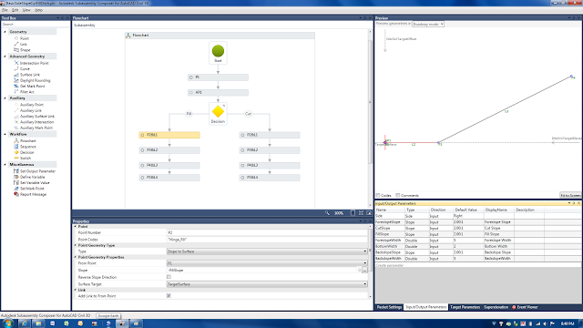
The left hand side contains items in your tool box. If you're familiar with looking through the help menus of various "out of the box" subassemblies, then many of these items will make sense to you.
The center of the window contains the subassembly flowchart. This area helps you visualize how the tools chosen from the tool box relate to one another. From a user standpoint, keeping things clean and organized will make creating a subassmebly much easier. The window directly below the flowchart contains the properties of the tools used. Simply click on an item, and the properties of that item show below.
The lower right window contains several tabs. The first tab, "Packet Settings" allows you to add a subassembly name (referenced in Civil 3D tool space), description of the subassmebly (again referenced in Civil 3D tool space), a help file (PDF, DOCX, or other), and graphic image (for viewing in Civil 3D tool space). Note that the help menu currently does not work for custom subassemblies within Civil 3D; this is a known bug that has not been fixed as of yet.
The next tab is for Input/Output paramters, these show up under subassembly properties, parameters tab within Civil 3D and allow the end user to enter custom values for the components designed in subassembly composer.
The third tab is for Target Parameters such as surfaces, offset targets, and elevation targets. The fourth tab contains super elevation data should that be needed, and the last tab is for the event viewer. I have only dealt with the first three tabs thus far.
The upper right window, called the preview, is probably one of the most helpful areas of the program. This area displays what the subassembly you are creating should look like, with a few limitations. Items I've noticed are when you apply a surface target, an offset targe, or an offset elevation target to the subassembly,the display changes per the preview settings, on the Target Parameters tab mentioned above. Thus causing the display of the design subassembly to appear differently than you'd expect. I'd recommend adding offset and elevation targets into the subassembly design last to avoid this.
The help menu of SAC is pretty good. It seems to be a forum where users can add information, yet with some sort of control as to what information is added. There are several packet files out there for download to visually see how to use each tool. This was probably the best way that I learned how to use the program. Open up one of the PKT files and view the data, click through the various tools and notice the properties programmed for each. Another good method in learning the software is to try and create one of the simple "out of the box" subassemblies within subassembly composer.
Creating a Subassembly
Firstly, in creating your own subassembly, you have to have a great inspiring idea. However, be sure to not pick something too difficult to handle, or you can quickly become disatissfied that your custom subassembly does not work. My first subassembly turned out to be too difficult to achieve at first, so I had to find another that I could actually complete.
I have been using the Civil 3D subassembly BasicSideSlopeCutDitch subassembly for quite a while and have found it extremely useful in roadway design. In more than one circumstance, engineers have requested that I carry the channel along the toe of the fill slope to pick up additional drainage (as shown in the image below). This can be a difficult process without the use of SAC, basically adding a corridor, then grading in an additional channel with grading groups or corridors, and pasting surfaces together. Thus I had the idea to recreate the BasicSideSlopeCutDitch, but modify it to include a channel in the fill section.

The flowchart for this subassembly is shown in the SAC overview image above and basically begins with a point that would be the hinge point of the subassembly and setting a target surface in the target parameters (set the surface preview to something greater than 0, while point 1 should be a 0,0. Next add in an auxiallry point, auxillary tools are temporary calculation tools and do not show up in Civil 3D visibly. The auxiallry point, needs to be set on the target surface, thus the properties type should be set to "Delta X on Surface", form point can either be point 1 or origin, Delta X would be 0, surface target is the target surface.
Next add in a decision; this is a conditional tool allowing you to provide input for a true/false situations. We need to tell the subassembly to determine if it is in a cut or fill situation. Under the properties of the decision the conditional value needs to check both the auxillary point 1 and point 1 Y values in relation to the target surface. Thus if you type "AP1.Y<P1.Y" you are telling the subassembly that if the distance to surface of the auxillary point is less than the distance to surface of the point, then perform the true option, if not perform the false option. The false option can be renamed to Cut and the true option can be renamed to fill, for organization. The left side of the decision tool is always the true value and the right side is always the cut value.
Next add in a point for both the cut side and the fill side. Connect lines to each from each side of the decision tool, you should see the Fill and Cut text show up in the line. Before moving forward, we need to add in user inputs. Add the following user inputs with the columns in order following, name, type, direction, default value, display name:
- Side, Side, Input, Right, Side
- ForeslopeSlope, Slope, Input, 2.00:1, Foreslope Slope
- CutSlope, Slope, Input, 2.00:1, Cut Slope
- FillSlope, Slope, Input, 2.00:1, Fill Slope
- ForeslopeWidth, Double, Input, 5, Foreslope Width
- BottomWidth, Double, Input, 2, Bottom Width
- Backslope Slope, Slope, 2.00:1, Backslope Slope
- BackslopeWidth, Double, Input, 5, Backslope Width
Next, add in points so there are a total of 4 points for each cut/fill situations; add flowchart arrow lines to connect each together. Points should reference the previous point, beginning with point 1. Lines should also be added to connect the points, notice the preview update as the information is added.
Next we need to added properties to each of the points starting with the first point on the cut side. This will be the first slope in the ditch, thus we know what the foreslope slope should be and we know what the foreslope width should be from the parameters created above. Make the point type to be "Slope and Delta X", set the slope to "-ForeslopeSlope", and the Delta X to "ForeslopeWidth". Next we need to establish the bottom of the ditch. This we know the bottom width and the bottom is flat, thus we can use the type "Angle and Delta X" where the angle will be "0" and the Delta X will be "BottomWidth". The next segment is the backslope of the channel and should be programmed similar to the foreslope and the last segment will tie from the top of the backslope to the surface. This segment will have a type of "Slope to Surface" using the CutSlope parameter as the slope and the target surface parameter as the surface target. The preview window should be taking shape now.
The fill slope side will be very similar to the cut slope side, however, the first segment should target the target surface at the fill slope first, then proceed into the foreslope of the channel, add in the bottom width, then target the target surface a second time to close the channel. This will not need a backslope as if a backslope is added, there is the possibility of passing the target surface and thus creating a berm, blocking drainage.
Final cleanup of the subassmebly should involve going through each of the points and lines and adding in point codes and codes for the objects. These should be entered in a similar fashion, ie "Top" and "Datum" should be added to all to create a top surface and datum surface on the subassembly.
Recommended Organizational Methods
For ease on end users, I recommend that prior to finalizing your subassemblies, study the help menu of similar "out of the box" subassemblies and use the same format Autodesk does for Input/Output Parameters, Targer Parameters, Point Codes, and Codes. Keeping various tools in line with one another in the flowchart will make it much easier to follow while programming. Click on a tool and drag, or use the arrow keys for a more refined movement.
Help menues should be made up to look similar to the "out of the box" help menus, at a minimum to provide the same type of information, schematics, and order.
Icons should be of the same format as ones provided. Starting with an "out of the box" icon is a great way to develop a nice looking icon. Program icons can be found here: C:\ProgramData\Autodesk\C3D 2011\enu\Tool Catalogs\Road Catalog\Images
Using the Subassembly in Civil 3D
Using the subassembly in Civil 3D is pretty easy. Simply right click on your tool palette, add a new custom palette, and import subassemblies. Browse to the PKT file saved by subassembly composer, select, and hit ok. Subassembly is now ready for use on the palette the same way all others are used.
Other users who do not have Subassembly Composer installed will need to download and install a patch from Autodesk.


