
Wednesday, February 29, 2012
Chicago Civil 3D User Group
Since moving to Chicago, I've been looking to get involved and interact with other Civil 3D and CAD users and have been unable to find a professional group to join. So, I am starting one!! If you know of anyone in the Chicago region that uses the software interested in joining, please direct them to the LinkedIn group called "Chicago Civil 3D User Group". Looking to have the first group meeting sometime in March.


Autodesk Subassembly Composer for AutoCAD Civil 3D
For those of you Civil 3D users that are big fans of corridors, like me, Autodesk has unveiled the new Subassembly Composer (SAC) recently. I had taken a couple overview classes at Autodesk University this last year, and have been using ever since. For me, SAC brings a whole fresh new aspect to Civil 3D. SAC allows users to create their own fully functioning custom subassemblies that can range from very simplistic to extremely complicated with various programming built in. These custom subassemlies can be huge time savers on projects.
Subassembly Composer Overview
The SAC program has a fairly simplistic interface with various panels that can be moved around the screen for customization. I'd recommend leaving everything where it is, as it makes sense, everything seen is used. See image below.
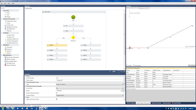
The left hand side contains items in your tool box. If you're familiar with looking through the help menus of various "out of the box" subassemblies, then many of these items will make sense to you.
The center of the window contains the subassembly flowchart. This area helps you visualize how the tools chosen from the tool box relate to one another. From a user standpoint, keeping things clean and organized will make creating a subassmebly much easier. The window directly below the flowchart contains the properties of the tools used. Simply click on an item, and the properties of that item show below.
The lower right window contains several tabs. The first tab, "Packet Settings" allows you to add a subassembly name (referenced in Civil 3D tool space), description of the subassmebly (again referenced in Civil 3D tool space), a help file (PDF, DOCX, or other), and graphic image (for viewing in Civil 3D tool space). Note that the help menu currently does not work for custom subassemblies within Civil 3D; this is a known bug that has not been fixed as of yet.
The next tab is for Input/Output paramters, these show up under subassembly properties, parameters tab within Civil 3D and allow the end user to enter custom values for the components designed in subassembly composer.
 The third tab is for Target Parameters such as surfaces, offset targets, and elevation targets. The fourth tab contains super elevation data should that be needed, and the last tab is for the event viewer. I have only dealt with the first three tabs thus far.
The upper right window, called the preview, is probably one of the most helpful areas of the program. This area displays what the subassembly you are creating should look like, with a few limitations. Items I've noticed are when you apply a surface target, an offset targe, or an offset elevation target to the subassembly,the display changes per the preview settings, on the Target Parameters tab mentioned above. Thus causing the display of the design subassembly to appear differently than you'd expect. I'd recommend adding offset and elevation targets into the subassembly design last to avoid this.
The help menu of SAC is pretty good. It seems to be a forum where users can add information, yet with some sort of control as to what information is added. There are several packet files out there for download to visually see how to use each tool. This was probably the best way that I learned how to use the program. Open up one of the PKT files and view the data, click through the various tools and notice the properties programmed for each. Another good method in learning the software is to try and create one of the simple "out of the box" subassemblies within subassembly composer.
Creating a Subassembly
Firstly, in creating your own subassembly, you have to have a great inspiring idea. However, be sure to not pick something too difficult to handle, or you can quickly become disatissfied that your custom subassembly does not work. My first subassembly turned out to be too difficult to achieve at first, so I had to find another that I could actually complete.
I have been using the Civil 3D subassembly BasicSideSlopeCutDitch subassembly for quite a while and have found it extremely useful in roadway design. In more than one circumstance, engineers have requested that I carry the channel along the toe of the fill slope to pick up additional drainage (as shown in the image below). This can be a difficult process without the use of SAC, basically adding a corridor, then grading in an additional channel with grading groups or corridors, and pasting surfaces together. Thus I had the idea to recreate the BasicSideSlopeCutDitch, but modify it to include a channel in the fill section.

The flowchart for this subassembly is shown in the SAC overview image above and basically begins with a point that would be the hinge point of the subassembly and setting a target surface in the target parameters (set the surface preview to something greater than 0, while point 1 should be a 0,0. Next add in an auxiallry point, auxillary tools are temporary calculation tools and do not show up in Civil 3D visibly. The auxiallry point, needs to be set on the target surface, thus the properties type should be set to "Delta X on Surface", form point can either be point 1 or origin, Delta X would be 0, surface target is the target surface.
Next add in a decision; this is a conditional tool allowing you to provide input for a true/false situations. We need to tell the subassembly to determine if it is in a cut or fill situation. Under the properties of the decision the conditional value needs to check both the auxillary point 1 and point 1 Y values in relation to the target surface. Thus if you type "AP1.Y<P1.Y" you are telling the subassembly that if the distance to surface of the auxillary point is less than the distance to surface of the point, then perform the true option, if not perform the false option. The false option can be renamed to Cut and the true option can be renamed to fill, for organization. The left side of the decision tool is always the true value and the right side is always the cut value.
Next add in a point for both the cut side and the fill side. Connect lines to each from each side of the decision tool, you should see the Fill and Cut text show up in the line. Before moving forward, we need to add in user inputs. Add the following user inputs with the columns in order following, name, type, direction, default value, display name:
Next we need to added properties to each of the points starting with the first point on the cut side. This will be the first slope in the ditch, thus we know what the foreslope slope should be and we know what the foreslope width should be from the parameters created above. Make the point type to be "Slope and Delta X", set the slope to "-ForeslopeSlope", and the Delta X to "ForeslopeWidth". Next we need to establish the bottom of the ditch. This we know the bottom width and the bottom is flat, thus we can use the type "Angle and Delta X" where the angle will be "0" and the Delta X will be "BottomWidth". The next segment is the backslope of the channel and should be programmed similar to the foreslope and the last segment will tie from the top of the backslope to the surface. This segment will have a type of "Slope to Surface" using the CutSlope parameter as the slope and the target surface parameter as the surface target. The preview window should be taking shape now.
The fill slope side will be very similar to the cut slope side, however, the first segment should target the target surface at the fill slope first, then proceed into the foreslope of the channel, add in the bottom width, then target the target surface a second time to close the channel. This will not need a backslope as if a backslope is added, there is the possibility of passing the target surface and thus creating a berm, blocking drainage.
Final cleanup of the subassmebly should involve going through each of the points and lines and adding in point codes and codes for the objects. These should be entered in a similar fashion, ie "Top" and "Datum" should be added to all to create a top surface and datum surface on the subassembly.
Recommended Organizational Methods
For ease on end users, I recommend that prior to finalizing your subassemblies, study the help menu of similar "out of the box" subassemblies and use the same format Autodesk does for Input/Output Parameters, Targer Parameters, Point Codes, and Codes. Keeping various tools in line with one another in the flowchart will make it much easier to follow while programming. Click on a tool and drag, or use the arrow keys for a more refined movement.
Help menues should be made up to look similar to the "out of the box" help menus, at a minimum to provide the same type of information, schematics, and order.
Icons should be of the same format as ones provided. Starting with an "out of the box" icon is a great way to develop a nice looking icon. Program icons can be found here: C:\ProgramData\Autodesk\C3D 2011\enu\Tool Catalogs\Road Catalog\Images
Using the Subassembly in Civil 3D
Using the subassembly in Civil 3D is pretty easy. Simply right click on your tool palette, add a new custom palette, and import subassemblies. Browse to the PKT file saved by subassembly composer, select, and hit ok. Subassembly is now ready for use on the palette the same way all others are used.
Other users who do not have Subassembly Composer installed will need to download and install a patch from Autodesk.
Subassembly Composer Overview
The SAC program has a fairly simplistic interface with various panels that can be moved around the screen for customization. I'd recommend leaving everything where it is, as it makes sense, everything seen is used. See image below.

The left hand side contains items in your tool box. If you're familiar with looking through the help menus of various "out of the box" subassemblies, then many of these items will make sense to you.
The center of the window contains the subassembly flowchart. This area helps you visualize how the tools chosen from the tool box relate to one another. From a user standpoint, keeping things clean and organized will make creating a subassmebly much easier. The window directly below the flowchart contains the properties of the tools used. Simply click on an item, and the properties of that item show below.
The lower right window contains several tabs. The first tab, "Packet Settings" allows you to add a subassembly name (referenced in Civil 3D tool space), description of the subassmebly (again referenced in Civil 3D tool space), a help file (PDF, DOCX, or other), and graphic image (for viewing in Civil 3D tool space). Note that the help menu currently does not work for custom subassemblies within Civil 3D; this is a known bug that has not been fixed as of yet.
The next tab is for Input/Output paramters, these show up under subassembly properties, parameters tab within Civil 3D and allow the end user to enter custom values for the components designed in subassembly composer.

The upper right window, called the preview, is probably one of the most helpful areas of the program. This area displays what the subassembly you are creating should look like, with a few limitations. Items I've noticed are when you apply a surface target, an offset targe, or an offset elevation target to the subassembly,the display changes per the preview settings, on the Target Parameters tab mentioned above. Thus causing the display of the design subassembly to appear differently than you'd expect. I'd recommend adding offset and elevation targets into the subassembly design last to avoid this.
The help menu of SAC is pretty good. It seems to be a forum where users can add information, yet with some sort of control as to what information is added. There are several packet files out there for download to visually see how to use each tool. This was probably the best way that I learned how to use the program. Open up one of the PKT files and view the data, click through the various tools and notice the properties programmed for each. Another good method in learning the software is to try and create one of the simple "out of the box" subassemblies within subassembly composer.
Creating a Subassembly
Firstly, in creating your own subassembly, you have to have a great inspiring idea. However, be sure to not pick something too difficult to handle, or you can quickly become disatissfied that your custom subassembly does not work. My first subassembly turned out to be too difficult to achieve at first, so I had to find another that I could actually complete.
I have been using the Civil 3D subassembly BasicSideSlopeCutDitch subassembly for quite a while and have found it extremely useful in roadway design. In more than one circumstance, engineers have requested that I carry the channel along the toe of the fill slope to pick up additional drainage (as shown in the image below). This can be a difficult process without the use of SAC, basically adding a corridor, then grading in an additional channel with grading groups or corridors, and pasting surfaces together. Thus I had the idea to recreate the BasicSideSlopeCutDitch, but modify it to include a channel in the fill section.

The flowchart for this subassembly is shown in the SAC overview image above and basically begins with a point that would be the hinge point of the subassembly and setting a target surface in the target parameters (set the surface preview to something greater than 0, while point 1 should be a 0,0. Next add in an auxiallry point, auxillary tools are temporary calculation tools and do not show up in Civil 3D visibly. The auxiallry point, needs to be set on the target surface, thus the properties type should be set to "Delta X on Surface", form point can either be point 1 or origin, Delta X would be 0, surface target is the target surface.
Next add in a decision; this is a conditional tool allowing you to provide input for a true/false situations. We need to tell the subassembly to determine if it is in a cut or fill situation. Under the properties of the decision the conditional value needs to check both the auxillary point 1 and point 1 Y values in relation to the target surface. Thus if you type "AP1.Y<P1.Y" you are telling the subassembly that if the distance to surface of the auxillary point is less than the distance to surface of the point, then perform the true option, if not perform the false option. The false option can be renamed to Cut and the true option can be renamed to fill, for organization. The left side of the decision tool is always the true value and the right side is always the cut value.
Next add in a point for both the cut side and the fill side. Connect lines to each from each side of the decision tool, you should see the Fill and Cut text show up in the line. Before moving forward, we need to add in user inputs. Add the following user inputs with the columns in order following, name, type, direction, default value, display name:
- Side, Side, Input, Right, Side
- ForeslopeSlope, Slope, Input, 2.00:1, Foreslope Slope
- CutSlope, Slope, Input, 2.00:1, Cut Slope
- FillSlope, Slope, Input, 2.00:1, Fill Slope
- ForeslopeWidth, Double, Input, 5, Foreslope Width
- BottomWidth, Double, Input, 2, Bottom Width
- Backslope Slope, Slope, 2.00:1, Backslope Slope
- BackslopeWidth, Double, Input, 5, Backslope Width
Next we need to added properties to each of the points starting with the first point on the cut side. This will be the first slope in the ditch, thus we know what the foreslope slope should be and we know what the foreslope width should be from the parameters created above. Make the point type to be "Slope and Delta X", set the slope to "-ForeslopeSlope", and the Delta X to "ForeslopeWidth". Next we need to establish the bottom of the ditch. This we know the bottom width and the bottom is flat, thus we can use the type "Angle and Delta X" where the angle will be "0" and the Delta X will be "BottomWidth". The next segment is the backslope of the channel and should be programmed similar to the foreslope and the last segment will tie from the top of the backslope to the surface. This segment will have a type of "Slope to Surface" using the CutSlope parameter as the slope and the target surface parameter as the surface target. The preview window should be taking shape now.
The fill slope side will be very similar to the cut slope side, however, the first segment should target the target surface at the fill slope first, then proceed into the foreslope of the channel, add in the bottom width, then target the target surface a second time to close the channel. This will not need a backslope as if a backslope is added, there is the possibility of passing the target surface and thus creating a berm, blocking drainage.
Final cleanup of the subassmebly should involve going through each of the points and lines and adding in point codes and codes for the objects. These should be entered in a similar fashion, ie "Top" and "Datum" should be added to all to create a top surface and datum surface on the subassembly.
Recommended Organizational Methods
For ease on end users, I recommend that prior to finalizing your subassemblies, study the help menu of similar "out of the box" subassemblies and use the same format Autodesk does for Input/Output Parameters, Targer Parameters, Point Codes, and Codes. Keeping various tools in line with one another in the flowchart will make it much easier to follow while programming. Click on a tool and drag, or use the arrow keys for a more refined movement.
Help menues should be made up to look similar to the "out of the box" help menus, at a minimum to provide the same type of information, schematics, and order.
Icons should be of the same format as ones provided. Starting with an "out of the box" icon is a great way to develop a nice looking icon. Program icons can be found here: C:\ProgramData\Autodesk\C3D 2011\enu\Tool Catalogs\Road Catalog\Images
Using the Subassembly in Civil 3D
Using the subassembly in Civil 3D is pretty easy. Simply right click on your tool palette, add a new custom palette, and import subassemblies. Browse to the PKT file saved by subassembly composer, select, and hit ok. Subassembly is now ready for use on the palette the same way all others are used.
Other users who do not have Subassembly Composer installed will need to download and install a patch from Autodesk.
Saturday, December 31, 2011
It's Been a While - I've Moved and Went to AU 2011
Well it's been a while since I've last posted; it has been a busy 3-4 months. I am no longer living in Pittsburgh, PA, and am now living in Chicago, IL. Chicago is a great city and has been my wife and my dream to live here for several years. We love the architecture, culture, and business that Chicago brings. Chicago is also closer to home for us, which is mid-Michigan area.
Along with the business of moving, we had several holidays and Autodesk University, which all of it has made it difficult to post. This year was my fifth Autodesk University, although I hadn't been to one since 2008. The conference was great. I learned some new techniques in the software and met a lot of great people. I was also able to update my certifications; thus I am now a Certified Professional in AutoCAD and AutoCAD Civil3D 2012.
The best part of AU 2011 and the most valuable takeaway that I received this year was the new Subassembly Composer. I'll be writing up a separate blog post on this topic as I have now been able to create some of my own subassemblies.
Along with the business of moving, we had several holidays and Autodesk University, which all of it has made it difficult to post. This year was my fifth Autodesk University, although I hadn't been to one since 2008. The conference was great. I learned some new techniques in the software and met a lot of great people. I was also able to update my certifications; thus I am now a Certified Professional in AutoCAD and AutoCAD Civil3D 2012.
The best part of AU 2011 and the most valuable takeaway that I received this year was the new Subassembly Composer. I'll be writing up a separate blog post on this topic as I have now been able to create some of my own subassemblies.
Sunday, August 14, 2011
Civil3D Surfaces with Contour Data
I just read a great post by Brian Hailey from his Civil3D plus blog regarding adding contour data to surfaces. He has some great points. If you're like me and the rest of the Civil3D world, we tend to use the items straight out of the box. Along with that, the software works quickly and we don't take enough time to truly analyze our surfaces and ensuring triangulation. Take a look at his blog post and see test the results for your selves!!
http://civil3dplus.wordpress.com/2011/08/13/adding-contours-to-a-surface-youre-doing-it-wrong/#comment-2862
http://civil3dplus.wordpress.com/2011/08/13/adding-contours-to-a-surface-youre-doing-it-wrong/#comment-2862
Friday, July 15, 2011
Autodesk Certifications
Well, as promised, I would let everyone know if I passed the Associate and Professional exams for Civil3D 2010, and I have. The tests were difficult, and really made you think. Personally, I thought the Professional exam was easier than the Associate. In the Professional exam, you need to use the software itself to answer the questions, thus you are free to figure out the problem. The onlly issue there is, the test is timed, leaving you scrambling at the end to answer the questions - yes I was scrambling and my pulse beating hard!!
The Associate exam consists of multiple choice questions, ranging from true and false to select 3 out of the 5 that make the most sense. These questions are difficult!! You really need to know the software, as many of them require the technical jargon that even I tend to forget.
All in all it was a great day of test taking, with great results. Now to look forward to taking the 2011 version, in which the passing scores are higher.
![]()
![]()
The Associate exam consists of multiple choice questions, ranging from true and false to select 3 out of the 5 that make the most sense. These questions are difficult!! You really need to know the software, as many of them require the technical jargon that even I tend to forget.
All in all it was a great day of test taking, with great results. Now to look forward to taking the 2011 version, in which the passing scores are higher.


Monday, July 11, 2011
Civil3D PDF Capabilities
I ran across an interesting item within Civil3D 2010 that I did not realize. I knew that there was the option of inserting a PDF, but I did not realize the ability to snap to PDF linework or the layer control. These options come can come in handy when dealing with PDF images. For those, like me, behind the software curve with Autodesk products, here are some highlights of the PDF capabilities.
Once the PDF is inserted to your drawing, select the PDF. This can be done different than working with images. CAD recoginizes the linework, thsu you can select the PDF by clicking on the linework as opposed to having to pick the outside frame of a normal image, saving time from panning and zooming. Next you should see the ribbon update to the "PDF Underlay" toolbar. Here there is an option to "Enable Snaps." Once enabled you'll be able to snap to the linework.
![]()
Two buttons to the right, is the "Edit Layers" button. This will open a dialoge box displaying the layer names of the PDF. Use the lightbulbs to turn on and off the layers. Notice that in the image below, the contours have been shut off using this option.
![]()
The image I am using was provided by a GIS department, thus I assume the layer naming comes from the creator's settings. I have not had the opportunity to test the snaps or layer control with PDFs made directly from CAD or other software, but I would expect it to work better with CAD/GIS.
Once the PDF is inserted to your drawing, select the PDF. This can be done different than working with images. CAD recoginizes the linework, thsu you can select the PDF by clicking on the linework as opposed to having to pick the outside frame of a normal image, saving time from panning and zooming. Next you should see the ribbon update to the "PDF Underlay" toolbar. Here there is an option to "Enable Snaps." Once enabled you'll be able to snap to the linework.

Two buttons to the right, is the "Edit Layers" button. This will open a dialoge box displaying the layer names of the PDF. Use the lightbulbs to turn on and off the layers. Notice that in the image below, the contours have been shut off using this option.

The image I am using was provided by a GIS department, thus I assume the layer naming comes from the creator's settings. I have not had the opportunity to test the snaps or layer control with PDFs made directly from CAD or other software, but I would expect it to work better with CAD/GIS.
Thursday, July 7, 2011
Autodesk Certifications
Over the last few years there has been an increasing hype regarding being certified in Autodesk products. I've talked with some that feel that it is a pointless effort to receive certification, but I however feel that it is becoming increasingly more popular with firms and Autodesk product users. I believe that it does truly test your knowledge or whether or not you truly know a product.
I recall a few years back sitting for the basic AutoCAD Certification exam offered at Autodesk University. Me thinking I was the greatest user out there (not really), sat for the exam thinking that it would be a breeze to pass. I found that as I went through the exam it became increasingly harder. The exam was timed, leaving you pushing your knowledge to the limits to deliver the answers in the fastest amount of time possible, while trying to maintain accuracy. Needless to say I walked away having missed one question from passing the exam.
Next week I have scheduled to sit for the Civil3D Associate and Professional Certifications. This round, I decided that maybe I should purchase the practice tests and really try and prepare for this - I mean Civil3D is far more complex than basic AutoCAD. I must say that some of the questions are difficult - and I've found that there are questions regarding areas of the software that I think are rarely used, such as Quantity Takeoff and Survey (being that surveyors are dragging to switch from LandDesktop). Thus these areas I found I really need to read up on a bit prior to the exam next week.
I believe that these exams will become increasingly more popular over the next few years, and I think it will be of great importance for us 'CAD' users to become certified to the 'Professional' level. And the best part is, the way the exams work is once you pass -- you're only certified for the version you took the exam on, thus leaving you to take the exam again for the next version. Autodesk does offer the ability to utilize their logos and the product names as marketing tools on business cards, emails, proposals, etc. should you pass the exam. I think this is a great way to market the CAD staff in corporations as they are typically hidden behind the scenes and often not advertised for the great amount of work that they actually do. Autodesk also provides a certification for hanging in your office or cubicle, and a search engine for finding certified users in the world. No, these aren't the coolest awards, but if you're looking to find out who the top CAD guys are in your office, these test will surely weed them out.
If you'd like to read more about the exams, or are looking to sit for one yourself, or would like to purchase the practice tests visit the link below:
https://autodesk.starttest.com/
As far as me telling you all my results, depends on if I pass it next week or not!!
I recall a few years back sitting for the basic AutoCAD Certification exam offered at Autodesk University. Me thinking I was the greatest user out there (not really), sat for the exam thinking that it would be a breeze to pass. I found that as I went through the exam it became increasingly harder. The exam was timed, leaving you pushing your knowledge to the limits to deliver the answers in the fastest amount of time possible, while trying to maintain accuracy. Needless to say I walked away having missed one question from passing the exam.
Next week I have scheduled to sit for the Civil3D Associate and Professional Certifications. This round, I decided that maybe I should purchase the practice tests and really try and prepare for this - I mean Civil3D is far more complex than basic AutoCAD. I must say that some of the questions are difficult - and I've found that there are questions regarding areas of the software that I think are rarely used, such as Quantity Takeoff and Survey (being that surveyors are dragging to switch from LandDesktop). Thus these areas I found I really need to read up on a bit prior to the exam next week.
I believe that these exams will become increasingly more popular over the next few years, and I think it will be of great importance for us 'CAD' users to become certified to the 'Professional' level. And the best part is, the way the exams work is once you pass -- you're only certified for the version you took the exam on, thus leaving you to take the exam again for the next version. Autodesk does offer the ability to utilize their logos and the product names as marketing tools on business cards, emails, proposals, etc. should you pass the exam. I think this is a great way to market the CAD staff in corporations as they are typically hidden behind the scenes and often not advertised for the great amount of work that they actually do. Autodesk also provides a certification for hanging in your office or cubicle, and a search engine for finding certified users in the world. No, these aren't the coolest awards, but if you're looking to find out who the top CAD guys are in your office, these test will surely weed them out.
If you'd like to read more about the exams, or are looking to sit for one yourself, or would like to purchase the practice tests visit the link below:
https://autodesk.starttest.com/
As far as me telling you all my results, depends on if I pass it next week or not!!
Subscribe to:
Posts (Atom)