Ran into this issue today and found out some interesting things... DEM files are only in metric, and thought C3D looks like it will convert on the fly, it will not. Found this blog for a solution.
Wednesday, July 11, 2012
Sunday, June 10, 2012
Civil 3D Find and Replace
Have you have had to rename a lot of different objects in Civil 3D? Or even have to change the descriptions?
For instance if you grade in a channel, you might make an alignment called Channel 5, which will also have a profile called Channel 5, which is on a profile view called Channel 5, which has an assembly called Channel 5, which all makes up a corridor called Channel 5, which has a corridor surface called Channel 5, which is pasted in a surface with a name reference to Channel 5. Then the engineer decides to renumber the channels... now your channel is Channel 100. Oh and there are about 15 different channels like this in your drawing. Good luck making sure everything reads as it should for the next person who uses the file.
This drove me to write a new command... C3D Find and Replace. I mean we can do a find and replace on regular text, why not on names and descriptions of objects???
Here are a few screenshots and a video showing the command in action.


You can watch the command in action here.
Thursday, June 7, 2012
Copy Surface Profile and Perform Raise/Lower Command
For those of you who read my posts, you probably have realized that I am all about less clicks and less menus. Civil3D can get somewhat confusing with the hidden operations to perform specific tasks. One of those very tasks that is somewhat hidden is the copy profile from surface procedure. There are a number of dialogs that you must go through and change a setting from static to dynamic, then get into the profile geometry editor, make a copy of the profile, go back and change the original profile's setting back to dynamic. You can find more detailed explanation of how to do this here and here.
In order to save more clicks and to speed up the process, I automated it programmatically. In this first image, the code begins with prompting for a selection of a profile. The 'prmpt.AddAllowedClass' line tells the software what type of object we are looking for. Anything other than a profile will return the reject message listed above. Next, this command was built for copying surface profiles, thus we perform an if/then statement on the selected profile type to verify the type is EG type. Note that the EG type stands for existing ground, though the user could create a profile on a proposed surface, and that would perform the same way.
Next we prompt for a raise or lower value. Upon copying, the command will adjust the PVI values automatically. This command also places a corresponding name and description on the profile, thus you'll see the if then statement checking the value of the typed in distance. If it's negative, it will display LOWERED, if it's positive it will display RAISED.
See the first image below.

The second image we arrive at the TRY statement, we have to gather information about the selected profile. So we store data about the profile in 'alignment', 'layerId', 'surfaceId', styleId' and 'labelSetId'. Note that these are all the items a profile requires to create from a surface. After gathering the previous profile information, I set the new profile name and the new profile description. I have set mine up to read as the following:
SelectedProfileName [COPY - RAISED/LOWERED XX'
The description will read something similar. Next we create the new profile as an ObjectId with all of the gathered information of the selected profile. Then we need to open that newly created profile and make sure the program knows to select it. Then I set the update mode to static and the description from the string above.
Now to adjust the PVIs. Here we perform a ForEach loop to check through all the PVIs in the new profile. We gather the current PVI elevation, add that to the selected value of offset (+/-), then change the PVI elevation. Finally we close the initial If/then statement with some kind of error message should the user pick a FG (finished grade profile), and commit the transaction.
See the second image below.

I'm fairly new to VB.net and the Civil3D API, so I don't know if this was the best method for this operation, but it definitely works!!
Wednesday, June 6, 2012
Eric Chappell's Blog: Upright Linetypes - Gotcha!
Here is a great post by Eric Chappell about 2012's upright linetype feature. Too bad I'm using 2011. So ready to switch!!
Eric Chappell's Blog: Upright Linetypes - Gotcha!: Recently we upgraded to Civil 3D 2012 and one of the things I was really excited about was actually an AutoCAD 2011 feature that enabled tex...
Eric Chappell's Blog: Upright Linetypes - Gotcha!: Recently we upgraded to Civil 3D 2012 and one of the things I was really excited about was actually an AutoCAD 2011 feature that enabled tex...
Sunday, June 3, 2012
Apply Surface Style to Multiple Surfaces in One Click
Civil 3D is a great tool. However, there are some commands and workflows that I come across during use that I think to myself "there has got to be a better way!!" One of those thoughts came to me a couple weeks ago in working with surfaces. The majority of my work is grading plans, thus I deal with a lot of surfaces. My grading plans typically consist of portions of my site (access road, pad, pits, channels, etc) all on separate surfaces, then pasted together into one compiled surface. This workflow works well when having to make modifications as you only have to work with a small area instead of a large surface.
The issue I found becomes in displaying these surfaces. The compiled surface is the one that is shown and all labels are based off of, the other surfaces are working surfaces and are only displayed when modifications are being made. Thus when coming into the drawing file I first have to turn the compiled surface to 'NO DISPLAY' then go through each of the working surfaces and turn them to a style that is displayed. Not a huge deal, but takes time and many clicks, so here's my thought - "there has to be a better way!!"
Well there is. Handle the surface displays programmatically with a new command. I'm simply calling this command 'Set Multiple Surface Styles' or from the command line, just type 'SMSS'.
Basically the command auto populates a pull down box with all the surface styles available in your current drawing and it populates a checkable list of surfaces in your current drawing. (Note: all surfaces are populated as there are four types in Civil 3D: Tin Surface, Grid Surface, Tin Volume Surface, and Grid Volume Surface.) Select the style desired and check which surfaces to apply it to, then click apply. For those that like to pick on screen, I have offered that option as well. For me personally, I've offered an expanded version of the command allowing for two different styles to be applied to surfaces all at once. (It's less clicks yet... I'm all about less clicks!!) I've also included a toolbar with a few buttons for formatting the lists; buttons include Sort, Check all, Uncheck all, and Invert Selection.
Here are some screen shots of the dialogs:

MAIN DIALOG

MAIN DIALOG

EXPANDED DIALOG
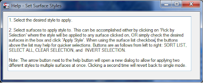
HELP MENU
As being fairly new to VB.net programming, this command was a bit difficult for me. I am currently using Civil 3D 2011, which is what the command was written in, however, it should work in older and newer versions - though it has not been tested. I initially thought I could write this command in VB.net, however the surfaces have not been fully exposed in 2011 from COM. So with a little help from JEFF_M on www.theswamp.org, he provided me with a method to call the vb.net surface and transfer it to a COM format for applying the style. Feel free to take a look at the posting here, if you'd like. This command opens up the door for other possibilities. I'm working on expanding the command for other style/object types and will post an updated version in the near future to look something like this:

FUTURE VERSION FOR ADDITIONAL STYLE/OBJECT TYPES
If you like this command and would like a copy of it you can find the DLL file here. Just type in NETLOAD in the command line and select the file. Then use "SMSS" to run the command.
If you like the command, but would like the source code for the command you can download the VB.net project here.
Feel free to let me know what you think of it!!
Thursday, May 24, 2012
Civil 3D Audit Commands
Have you ever run into major errors in your grading files and can't figure out what is wrong? Ever run the Audit command and it says surface error, then you look at the definition of the surface and it create a snapshot and no longer references actual feature lines, grading groups, etc.? What about disappearing feature lines and grading groups?
These are issues my colleagues and myself have ran into over the years. I have been looking for a fix for a while now, and I think I may have found a solution.
Here is a post by the CAD Geek referring to some of these issues, which then forwards you on to the Being Civil Blog post about Undocumented Commands, which then points to the (now documented) Autodesk page referring to these commands.
From what I understand, you would first run the 'AeccFindSiteOverlaps' command on each site. The command will tell you if there are erros and which of the following commands should be run to remove overlapping geometry: 'AeccRemoveDupFeatureLines', 'AeccRemoveAlignmentsFromSite', or 'AeccRemoveDupLotLines'.
Wednesday, May 16, 2012
Publishing Autodesk Civil3D Data into a 3D Web Viewer
I recently ran into a situation where I needed to allow multiple people access to a DWF file. You can easily email the file around to people, then they would need to install the free DWF viewer available on Autodesk website. From there they can open the file and view.
But what if that is just too many steps for the situation? Autodesk has a product called Autodesk Freewheel and can be found here. This allows you to post content to DWF files that are stored out on the web. Below are a couple of examples of these. The first is a 2D drawing package from the Autodesk Freewheel site. The second is an example of a 3D DWF I created from Civil3D with both Civil3D objects and basic AutoCAD objects, then published to a 3D DWF file.
In adding the file to the web, I first attempted using Google Docs which turned out to be unsuccessful. Google Docs which creates a hyperlink that no longer contains the DWF file name and only allows for the file to be downloaded for viewing. My next attempt was through Dropbox, which does work. I placed the file in my public folder and copied the link to the file. Dropbox also creates a separate hyperlink, but keeps the file extension allowing for Autodesk Freewheel to access the file.
Please note on the Autodesk Freewheel page that within the hyperlinks additional code is needed to set the view to start point. For 3D DWFs this can be quite nerve racking trying to set the view where you want it. Here is a good workflow I used to set the starting view.
1. Use Mozilla Firefox for your internet browser.
2. Load the viewer onto your webpage, then go view the webpage through Mozilla Firefox.
3. Set the view using the viewer to how you want it to start.
4. Right click on the view and go to "This Frame, View Frame Info" as shown in the image below.
5. When the window pops up, go to Media and browse through the view links until you find the last full path, as shown in the image below. This will be the settings for your current view.
6. Right click, and copy the path.
7. Update the path on your web page to the copied path. Note be sure that the beginning path first calls up the Autodesk Freewheel web program (ie. Everything before "path=", your model path should follow the "path=").
8. Go and verify that the page loads correctly.

STEP 4

STEP 5
Autodesk Freewheel also allows for a free rendering service that provides a link to your DWF model. Here is a sample of my 3D DWF rendered through the model.
Subscribe to:
Posts (Atom)